For 1990-2009 cars only
Removal Procedure
- Remove the left closeout/insulator panel. Refer to Instrument Panel Insulator Panel Replacement - Left Side .
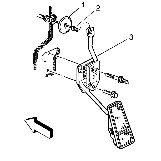
- Unseat snap retainer (1) from accelerator controls pedal lever.
- Remove the accelerator controls cable (2) from the accelerator pedal (3).
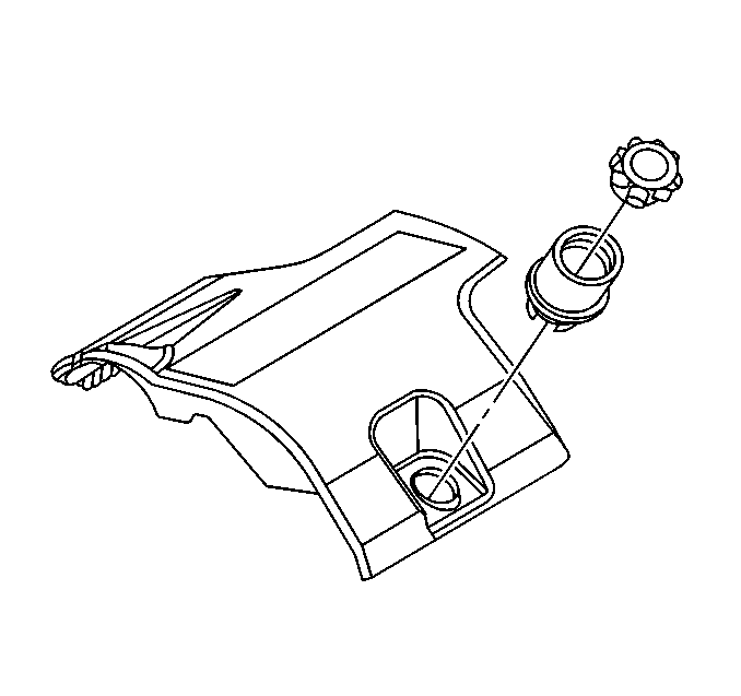
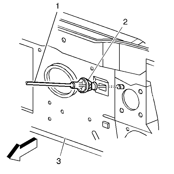
- Squeeze the accelerator controls cable (1) tangs (2) and push the accelerator cable through the bulkhead (3).
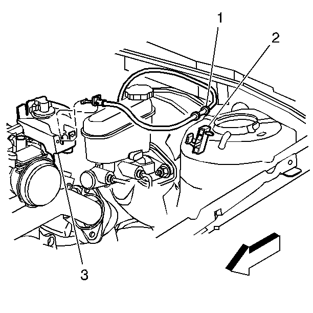
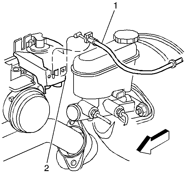
- Remove the accelerator controls cable (1) from the retaining clip (2) on the strut tower.
- Remove the fuel injector sight shield from the engine. Refer to Fuel Injector Sight Shield Replacement in Engine Mechanical.
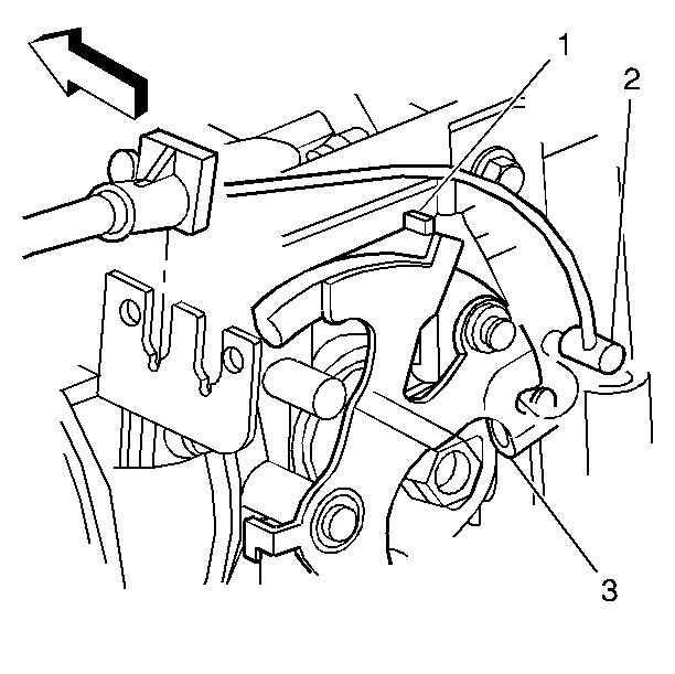
- Remove the accelerator controls cable (2) from the throttle body lever (3).
- Remove the accelerator controls cable (1) from the accelerator controls bracket (3).
Installation Procedure
Notice: Do not route flexible components (hoses, wires, conduits, etc.) within 50 mm (2 in) of moving parts unless flexible components can be securely fastened. This is necessary in order to prevent possible interference and damage to the component.
Important: Do not kink cable during installation.
- Install the accelerator controls cable (1) through the bulkhead (3).
- Install the accelerator controls cable tangs (2) through the bulkhead.
- Install the accelerator controls cable (2) through the slot in the accelerator controls pedal lever (3).
- Seat the snap retainer (1) in the accelerator controls pedal lever.
- Install the accelerator controls cable (2) to the throttle body lever (3).
- Install the accelerator controls cable (1) to the accelerator controls bracket (2).
- Install the accelerator controls cable (1) into the retaining clip (2) on the strut tower.
- Check for complete throttle opening and closing positions by operating the accelerator pedal. Also check for poor carpet fit under the accelerator pedal.
- Install the left closeout/insulator pane. Refer to Instrument Panel Insulator Panel Replacement - Left Side .
- Install the fuel injector sight shield from the engine. Refer to Fuel Injector Sight Shield Replacement in Engine Mechanical.
| 2.1. | Apply pressure to seat the grommet. |
| 2.2. | Ensure grommet is fully seated. |
Important: Assure that the cable is under the hook (1) in the throttle body lever.
Important: The throttle should operate freely, without binding, between full closed and wide open throttle.