Removal Procedure
Tools Required
J 34730 , Fuel Pressure Gauge
Caution: Provide additional support when a vehicle is on a hoist:
• Before removing parts, support the opposite end. This helps prevent
the vehicle from slipping off. • Before removing major components, chain the vehicle frame to the
hoist pads at the same end as the removal. This helps avoid a tip-off.
Notice: Do not attempt to straighten any kinked nylon fuel lines. Replace any kinked nylon fuel feed or return pipes in order to prevent damage to the vehicle.
- Relieve the fuel system fuel pressure. Refer to the Fuel Pressure Relief .
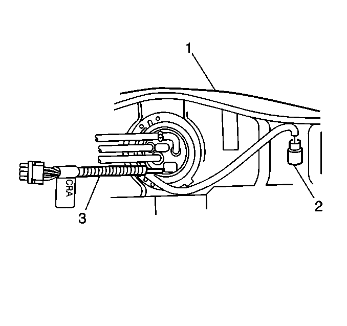
- Drain the fuel tank (1). Refer to Fuel Tank Draining .
- Raise the vehicle.
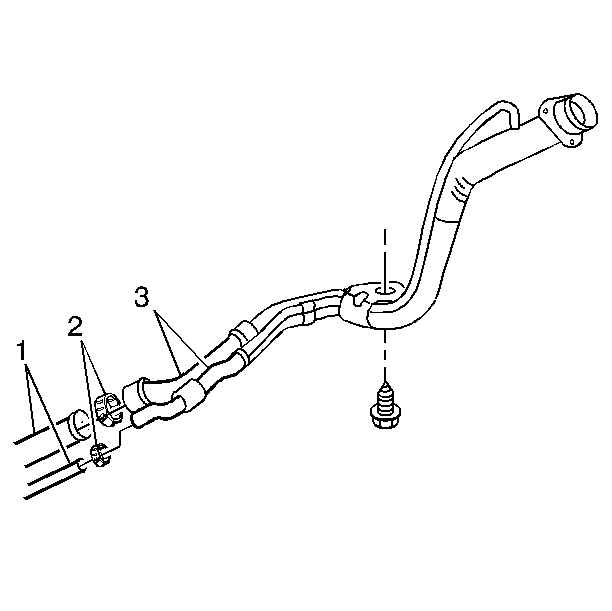
- Remove the fuel tank filler extension pipe EVAP pipe (1) clamp (2) from the fuel tank EVAP pipe (3).
- Remove the fuel tank filler extension pipe (1) clamps (2) from the fuel tank filler pipe (3).
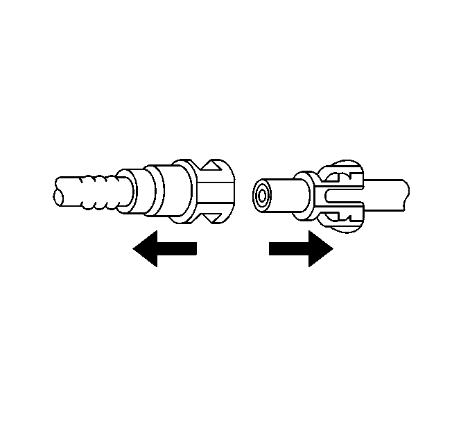
- Remove the quick-connect fittings at the fuel tank. Refer to Plastic Collar Quick Connect Fitting Service .
- Remove the rubber exhaust pipe hangers in order to allow the exhaust system to drop slightly.
- With the aid of an assistant, support the fuel tank and then remove the fuel tank strap attaching bolts which retain the fuel tank straps (1).
- Lower the fuel tank enough in order to disconnect and remove the fuel sender retaining clips.
- Remove the fuel tank from the vehicle and place the fuel tank in a suitable work area.
Caution: Provide additional support when a vehicle is on a hoist:
• Before removing parts, support the opposite end. This helps prevent
the vehicle from slipping off. • Before removing major components, chain the vehicle frame to the
hoist pads at the same end as the removal. This helps avoid a tip-off.
Notice: Cap the fittings and plug the holes when servicing the fuel system in order to prevent dirt and other contaminants from entering the open pipes and passages.
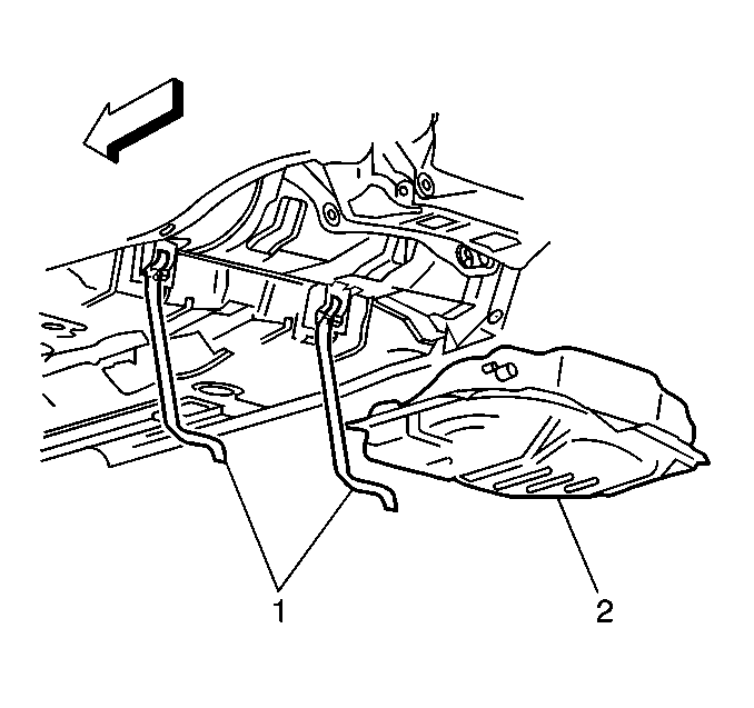
Notice: Do not bend the fuel tank straps as this may damage the straps.
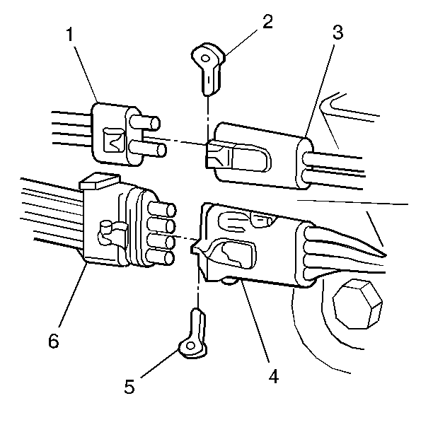
| 9.1. | Remove the retaining clip (2) on the fuel tank pressure sensor (3) electrical connector (1). |
| 9.2. | Remove the retaining clip (5) on the fuel sender assembly sensor (4) electrical connector (6). |
Disassemble Procedure
- If the fuel tank is not being replaced. Refer to the Installation Procedure.
- Disassemble the fuel sender assembly. Refer to Fuel Sender Assembly Replacement .
Assemble Procedure
- Install a new fuel sender O-ring.
- Assemble fuel sender assembly. Refer to Fuel Sender Assembly Replacement .
Important: Always replace the external fuel pump strainer when the fuel sender is removed.
Notice: Replace the fuel sender O-rings when re-installing the fuel sender in order to avoid damage to the fuel sender assembly.
Installation Procedure
Notice: Always re-attach the fuel lines and fuel filter with all original type fasteners and hardware.
Do not repair sections of fuel pipes.- Position and support the fuel tank (2), with the aid of an assistant.
- Install the fuel sender electrical connector (3).
- Install the fuel tank pressure sensor electrical connector (2).
- Install the fuel sender retaining clip (s).
- Install the fuel tank pressure sensor retaining clips.
- Install the fuel tank retaining strap (1) attaching bolts.
- Install the quick-connect fittings. Refer to Plastic Collar Quick Connect Fitting Service .
- Install the fuel tank filler extension pipe (1) to the fuel tank filler pipe (3).
- Install the EVAP fuel tank filler extension pipe (1) to the fuel tank filler pipe (3).
- Install the rubber exhaust pipe hangers.
- Lower the vehicle.
- Add fuel to the fuel tank.
- Install the fuel tank filler pipe cap.
- Install the negative battery cable. Refer to Battery Negative Cable Disconnection and Connection .
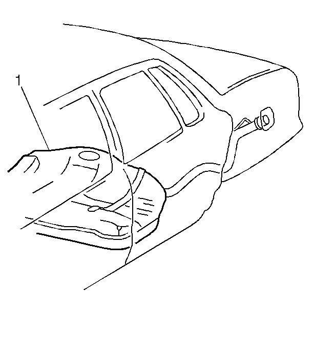
- Reinstall the fuel injector sight shield. Refer to Fuel Injector Sight Shield Replacement .
Notice: Use the correct fastener in the correct location. Replacement fasteners must be the correct part number for that application. Fasteners requiring replacement or fasteners requiring the use of thread locking compound or sealant are identified in the service procedure. Do not use paints, lubricants, or corrosion inhibitors on fasteners or fastener joint surfaces unless specified. These coatings affect fastener torque and joint clamping force and may damage the fastener. Use the correct tightening sequence and specifications when installing fasteners in order to avoid damage to parts and systems.
Tighten
Tighten the fuel tank retaining strap bolts to 34 N·m (25 lb ft).
Important: Do Not attempt to repair sections of nylon fuel pipes. If the nylon fuel pipes are damaged, replace them.
Tighten
Tighten the fuel tank filler extension pipe hose clamp (2) to 2.5 N·m
(22 lb in).
Tighten
Tighten the EVAP fuel tank filler extension pipe hose clamp to 2.5 N·m
(22 lb in).
| 14.1. | Turn the ignition switch ON for 2 seconds. |
| 14.2. | Turn the ignition switch OFF for 10 seconds. |
| 14.3. | Turn the ignition switch ON. |
| 14.4. | Check for fuel leaks. |
