CAMPAIGN: ANTI-LOCK BRAKE PRESSURE WARNING LIGHT

MODELS/YEARS: 1986 AND CERTAIN 1987 OLDSMOBILE NINETY-EIGHT REGENCYS EQUIPPED WITH ANTI-LOCK BRAKE SYSTEM
Condition:
---------
General Motors has determined that a defect which relates to motor vehicle safety may exist in some 1986 and 1987 Ninety-Eight Regencys equipped with Anti-Lock Brake System (ABS).
Involved vehicles may exhibit brake fluid seepage from the ABS pressure/warning switch which eventually can lead to loss of the brake system hydraulic pump motor. Loss of the hydraulic pump motor would, after accumulated pressure has been depleted (approximately 10-30 normal stops), result in a total loss of rear brakes as well as power assist to the front brakes. The red "Brake" warning light would, before accumulated pressure has been depleted, illuminate and stay ON. If this warning is not heeded, a loss of rear brakes at a time when minimum stopping distance is required could result in a vehicle crash.
Vehicles Involved
Certain 1986 and 1987 Ninety-Eight Regencys equipped with ABS brakes (JM4) within the following vehicle breakpoints:
Year Series Plant From Through and Including ---- ------ ----- ---- --------------------- 1986 "98" Orion Start of Production G4381271 1986 "98" Wentzville Start of Production G1342814 1987 "98" Orion Start of Production H4312651
Dealer Action
To correct this condition, dealers are to replace the pump motor relay and 30 amp ABS fuses on all vehicles involved. In addition, dealers are to inspect and replace, if required, the hydraulic pump and motor and/or pressure switch as instructed in the Service Procedure of this bulletin.
Dealers are to service all vehicles involved in this campaign, at no charge to owners, regardless of mileage, age of vehicle, or ownership. Whenever a vehicle subject to this campaign is taken into your new or used car inventory, dealers are to take the steps necessary to be sure the campaign correction has been made before reselling the vehicle.
In addition, dealers are to perform the campaign on all affected vehicles as they are brought in for any kind of service.
Service Procedure
1. Raise hood, install fender covers. Leave ignition key in OFF position, Disconnect battery cables from battery.
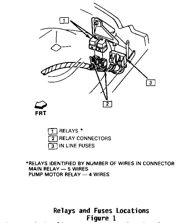
2. Replace the ABS pump motor relay, and both the ABS pump motor 30 amp fuse and the ABS main 30 amp fuse. The pump motor relay will have four wires in its connector. Relay and fuses are located on the left front of dash behind the strut tower (see Figure 1).
CAUTION:
RELAY MUST BE REINSTALLED ON BRACKET WITH CONNECTOR AT BOTTOM TO PREVENT WATER ENTRY. IF RELAY BRACKET MOUNTING IS DISTURBED, BRACKET MUST BE RESECURED TO FRONT OF DASH.
3. Visually inspect hydraulic pump and motor housing for any evidence of brake fluid seepage below the pressure switch. If any components require replacement, care should be taken to prevent brake fluid spillage onto the motor.
A. If any evidence of brake fluid seepage is indicated, perform the following steps as outlined in the 1987 Oldsmobile Ninety-Eight Chassis Service Manual, Volume 1, pages 5E - 5 & 6. If no seepage is indicated, proceed to Step 3B.
1. Replace the hydraulic pump and motor.
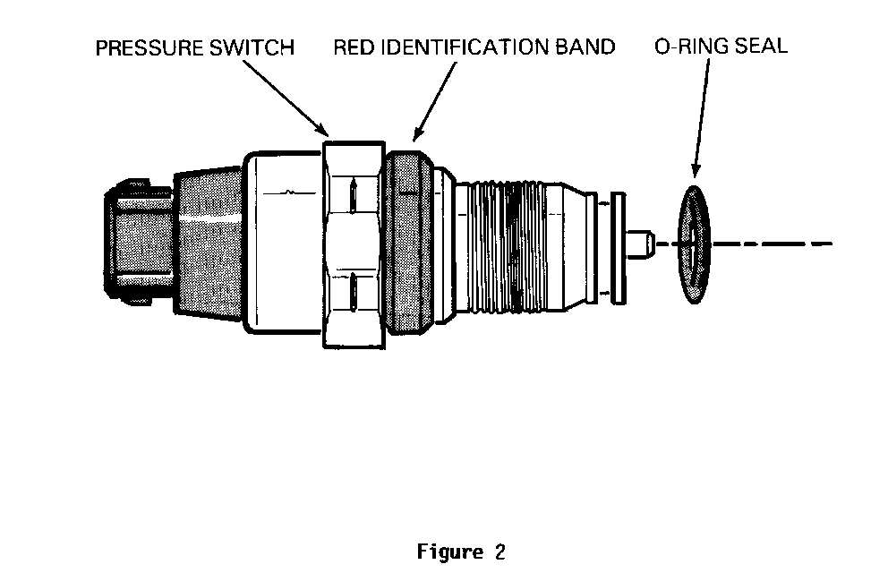
2. Inspect pressure switch for red plastic identification band (see Figure 2). If red band is observed, the switch requires replacement. If red band is not observed, the original switch must be transferred to the replacement pump and motor.
CAUTION:
FAILURE TO FULLY DEPRESSURIZE THE HYDRAULIC ACCUMULATOR BEFORE PERFORMING SERVICE OPERATIONS COULD RESULT IN INJURY TO SERVICE PERSONNEL AND DAMAGE TO PAINTED SURFACES.
B. If there is no evidence of brake fluid seepage, inspect only the pressure switch for red plastic identification band (see Figure 2). If red band is observed, the switch requires replacement. Follow pressure switch replacement procedure in 1987 Oldsmobile Ninety-Eight Chassis Service Manual, Volume 1, page 5E-6. If red band is not observed, proceed to Step 3C.
C. If visual inspection does not indicate any parts replacement except for relay and fuses replaced in Step 2, proceed to Step 5.
4. If pressure switch is replaced, without pump and motor replacement, check fluid level in reservoir and ensure that it is filled to mark. Do not overfill or underfill. Connect battery cables and turn ignition key to ON position until pump motor stops. Check for brake fluid leak.
USE ONLY DOT 3 BRAKE FLUID FROM A CLEAN, SEALED CONTAINER. DO NOT USE ANY FLUID FROM A CONTAINER WHICH IS WET WITH WATER. USE OF DOT 5 SILICONE FLUID IS NOT RECOMMENDED. INTERNAL DAMAGE TO THE PUMP COMPONENTS MAY RESULT,
If hydraulic pump and motor is replaced:
o Fill reservoir with brake fluid. Connect battery cables. o Turn ignition key to ON position until pump motor stops. o Check for brake fluid leak. o Turn ignition key OFF and discharge accumulator. See Checking and Filling in 1987 Oldsmobile Ninety-Eight Chassis Service Manual, Volume 1, page 5E-4. o Ensure that the brake fluid reservoir is filled to mark. Do not overfill or underfill.
5. Install a Campaign Identification Label
6. Connect battery cables if not previously connected in Step 4. Remove fender covers and close hood.
Campaign Identification Label
Each label provides a space to include the campaign number, the five (5) digit dealer code of the dealer performing the campaign service, and the date vehicle was campaigned. This information may be inserted with a typewriter or ballpoint pen. When installing label, clean the surface of the radiator support tie bar and apply the campaign label where it is readily visible.
Parts Information
Parts are to be obtained through GMSPO using the following part numbers:
Description Part Number ----------- ----------- Pressure (Warning) Switch 25530882 Hydraulic Pump and Motor 25528401 Pump Motor Relay 25525848 30 Amp Fuse (2) 12004011
It is anticipated that most cars will require a pressure warning switch, but that less than 20% will require a hydraulic pump and motor. All cars will require relay and fuses. Please adjust your orders accordingly for the hydraulic pump and motor.
To ensure these parts are obtained as soon as possible, they should be ordered from GM Service Parts Operations (GMSPO) on a C.I.O. order, with NO special instruction code; but order on an Advise Code (2).
Warranty Claim Information
List the one applicable labor operation. A separate repair order must be used for each vehicle. A completed warranty claim is to be kept as a permanent record of completion.
Labor Parts Failure Operation Labor Operation Allowance Code Number Hours --------- --------- ------- --------- -----
Inspect & Install:
1-Pump Motor Relay 25525848 ** 96 V4055 .2 2-30 amp fuses 12004011
Inspect & Install:
1-Pump Motor Relay 25525848 ** 96 V4056 .3 2-30 amp fuses 12004011 1-Pressure Warning Switch 25530882
Inspect & Install:
1-Pump Motor Relay 25525848 ** 96 V4057 .6 2-30 amp Fuses 12004011 1-Hydraulic Pump & motor 25528401
Inspect & Install:
1-Pump Motor Relay 25525848 ** 96 V4058 .7 2-30 amp Fuses 12004011 1-Pressure Warning Switch 25530882 1-Hydraulic Pump & Motor 25528401
* 0.1 hour for clerical administration may be added to the above operations. ** List current dealer price, plus 30%.


General Motors bulletins are intended for use by professional technicians, not a "do-it-yourselfer". They are written to inform those technicians of conditions that may occur on some vehicles, or to provide information that could assist in the proper service of a vehicle. Properly trained technicians have the equipment, tools, safety instructions and know-how to do a job properly and safely. If a condition is described, do not assume that the bulletin applies to your vehicle, or that your vehicle will have that condition. See a General Motors dealer servicing your brand of General Motors vehicle for information on whether your vehicle may benefit from the information.
