REVISED IGNITION SYSTEM DIAGNOSTIC PROCEDURES

1985 CALAIS EQUIPPED WITH 3.OL V-6 ENGINE (VIN CODE L)
The ignition system and certain driveability condition diagnostic procedures have been revised for 1985 Calais models equipped with a 3.OL V-6 (VIN Code L) engine.
Please update the applicable pages of your 1985 Firenza, Calais, Cutlass Ciera and Ninety-Eight Chassis Service Manual, Volume II with this revised information.
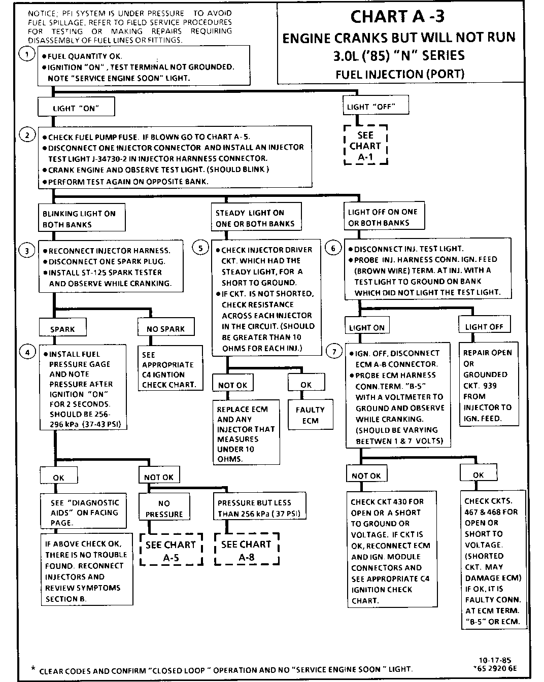
CHART A - 3 ENGINE CRANKS BUT WON'T RUN 3.OL ('85) "N" SERIES FUEL INJECTION (PORT)
CONDITION:
Engine cranks but won't run, or Engine may start, but immediately stops running. Battery condition and engine cranking speed are OK and there is adequate fuel in the tank.
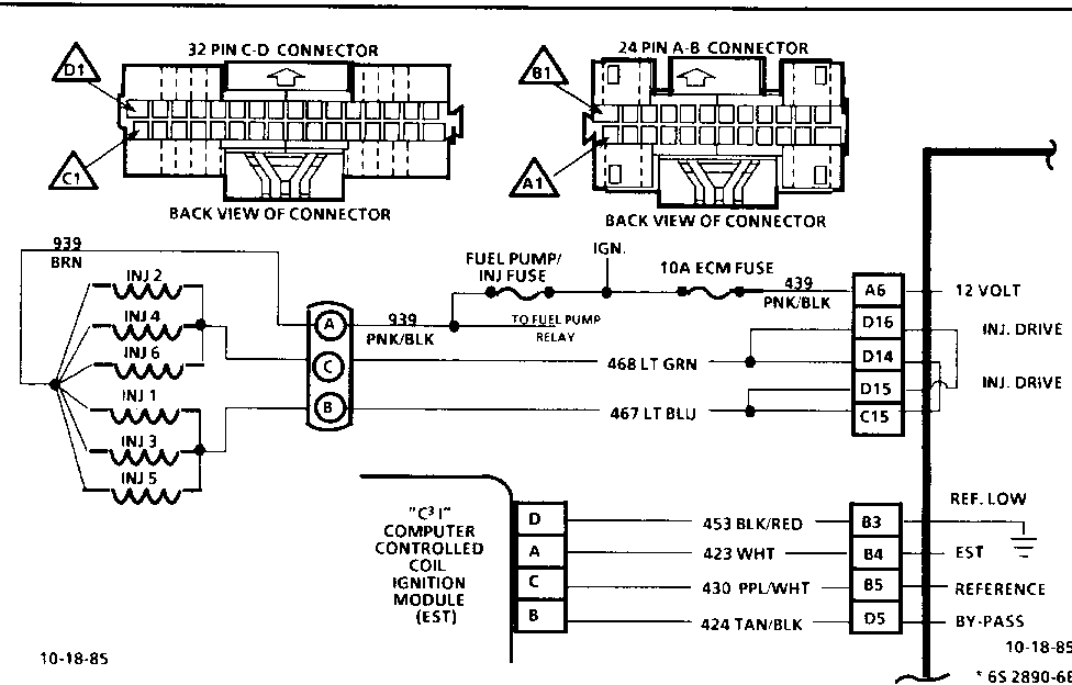
This engine is equipped with distributorless ignition system called "Computer Controlled Coil Ignition" (c 3 1). The EST and Bypass circuits operate in the same manner as in an HEI system.
1. A "SERVICE ENGINE SOON" light "ON" is a basic check for ignition and battery supply to the Electronic Control Module (ECM ).
2. Checks to see if the ECM is controlling the fuel injectors. A blinking test light at this point indicates the ECM is controlling the injectors and that ignition reference signal to the ECM is good.
3. Checks to see if problem is fuel or ignition related.
4. Checks to see if fuel pump and relay are operating correctly. Fuel pump should run for only 2 seconds after ignition "ON".
5. An injector driver circuit shorted to ground would result in the test light on steady and possibly a flooded engine. A shorted injector (less than 10 OHMS) could have caused an ECM failure.
6. Checks for ignition feed to injectors on each bank.
7. Checks to see if ECM is receiving reference signal from ignition system.
DIAGNOSTIC AIDS. Check For: - Open coolant sensor. - EGR sticking open. - TPS binding or sticking in wide open throttle position. - Water or foreign material in fuel. - A defective MAF Sensor may cause a no start or a stall after start.To determine if the sensor is causing the problem, disconnect it. The ECM will then use a default value for the sensor, and if the condition is corrected and the connections are OK, replace the sensor.
DETONATION /SPARK KNOCK
Definition: A mild to severe ping, usually worse under acceleration. The engine makes sharp metallic knocks that change with throttle opening. Sounds like popcorn popping.
* Check for obvious over heating problems: * Low coolant * Loose water pump belt * Restricted air flow to radiator, or restricted water flow through radiator. * Inoperative electric cooling fan circuit. See CHART C-12. * Check ignition timing. See Vehicle Emission Control Information label. * Check EGR system for not opening - CHART C-7, or C-7A. * Check ESC system for no retard - see CHART C5.
* Check fuel system pressure. See CHART A-7. * Remove carbon with top engine cleaner. Follow instructions on can. * Check for correct PROM. (See Service Bulletins) * Check for leaking valve oil seals. * Check for improper operation of transmission and TCC. * Check for incorrect basic engine parts such as cam, heads, pistons, etc. * Check for poor fuel quality, proper octane rating.
CUTS OUT, MISSES
Definition: Steady pulsation or jerking that follows engine speed, usually more pronounced as engine load increases. The exhaust has a steady spitting sound at idle or low speed.
* Perform careful visual (physical) check as described at start of Section B. * Misses At Idle: 1. With engine idling, disconnect IAC motor. Remove one spark plug wire at a time using insulated pliers.
2. If there is an RPM drop on all cylinders, go to ROUGH, UNSTABLE, OR INCORRECT IDLE, OR STALLING symptom. Reconnect TAC motor.
3. If there is no RPM drop on one or more cylinders, or excessive variation in drop, check for spark on the suspected cylinder(s) with J 26792 (ST-125) Spark tester or equivalent.
If spark exists: Inspect plugs for: - Cracks, Wear, Improper Gap - Burned Electrodes, or Heavy Deposits - Perform compression check on questionable cylinder.
If no spark on suspected cylinders: ON DISTRIBUTOR TYPE SYSTEM Check wire resistance (should not exceed 30,000 ohms), also check rotor and distributor cap. ON NON-DISTRIBUTOR SYSTEMS Ground the opposite plug wire of the effected coil pair. If tester now sparks replace the spark plug of the wire which was jumpered to ground. If tester still does not spark, refer to appropriate ignition chart in Section C4.
* Cuts Out Under Load: Test for spark on each wire with an J 26792 spark tester or equivalent. If there is spark on all cylinders, remove plugs and check for: - Cracks, Wear,lmproper Gap - Burned Electrodes, or Heavy Deposits
If no spark at plug(s): ON DISTRIBUTOR TYPE SYSTEM Check wire resistance (should not exceed 30,000 ohms), also check rotor and distributor cap. ON NON-DISTRIBUTOR SYSTEMS Ground the opposite plug wire of the effected coil pair. If tester now sparks replace the spark plug of the wire which was jumpered to ground. If tester still does not spark, refer to appropriate ignition chart in Section C4.
* If above checks did not correct problem, check the following: - Disconnect all injeetor harness connectors. Connect J-34730-2 Injector Test Light or equivalent 6 volt test light between the harness terminals of each injector connector and note light while cranking. If test light fails to blink at any connector, it is a faulty injector drive circuit harness, connector, or terminal. - Perform the Injector Balance Test. See CHART C-2A. - Visually inspect distributor cap and rotor for moisture, dust, cracks, burns, etc. Spray cap and plug wires with fine water mist to check for shorts. - Fuel System - Plugged fuel filter, water, low pressure. See CHART A-7 - Valve Timing - Remove rocker covers. Check for bent pushrods, worn rocker arms, broken valve springs, worn camshaft lobes. Repair as necessary. See Section 6A. - Perform compression check. - On C 3 I systems, a misfire may be caused by a misaligned crank sensor or bent vane on rotating disc. Inspect for proper clearance at each vane, approx. .030 " (.76mm). Sensor should be replaced if it shows evidence of rubbing.
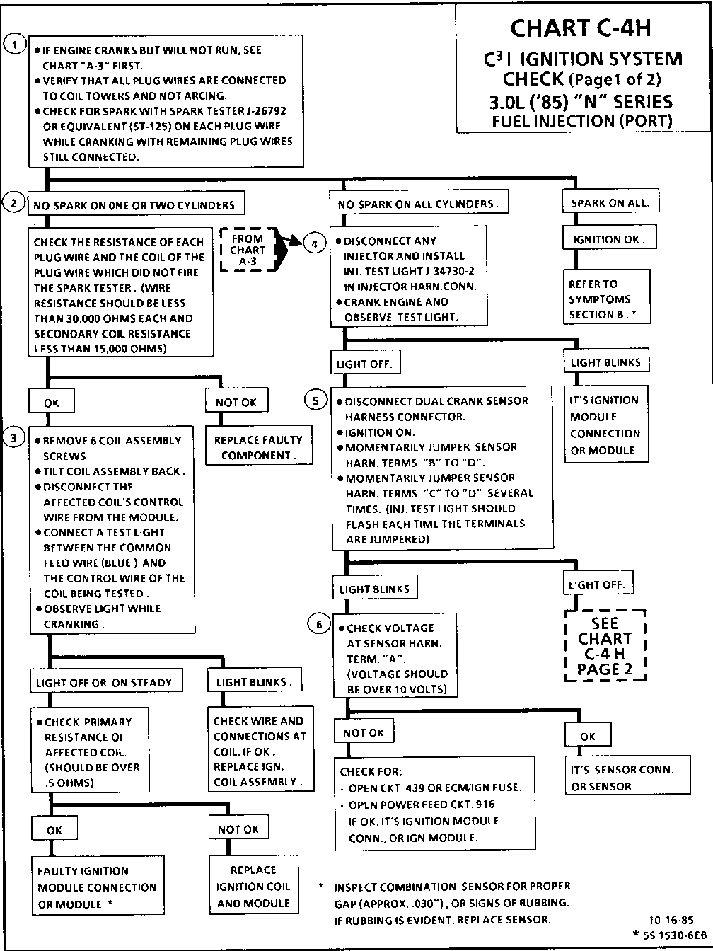
CHART C-4H C31 IGNITION SYSTEM CHECK (Page 1 of 2) 3.OL ('85) " N" SERIES
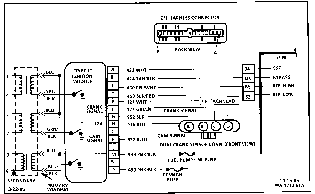
The C 3 I uses a waste spark method of distribution. In this type of system, the ignition module triggers the #1/4 coil pair resulting in both #1 and #4 spark plugs firing at the same time. #1 cylinder is on the compression stroke at the same time #4 is on the exhaust stroke, resulting in a lower energy requirement to fire #4 spark plug. This leaves the remainder of the high voltage to be used to fire #1 spark plug.
1. If a plug wire is open, the other plug on that coil should still fire at idle. The spark tester tests the ability of the system to produce at least 25,000 volts.
2. No spark on one cylinder may be caused by an open plug wire or secondary winding. therefore, both wires related to a coil and the secondary winding resistance should be checked. Resistance readings over the upper limit but not infinite will probably not cause a no start but may cause an engine miss under certain conditions.
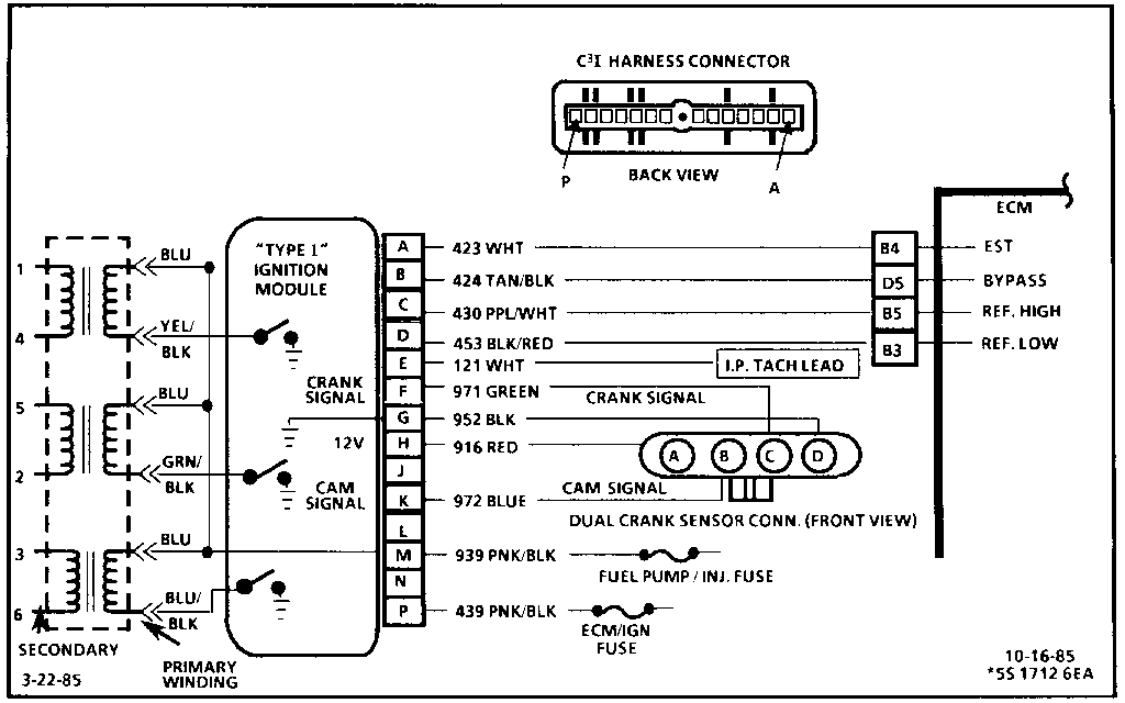
3. This tests the triggering circuit in the ignition module. A blinking light indicates the module is triggering. The diagram above shows the control wire color for each coil. For example, if testing why #1 plug did not fire, connect the test light between the blue feed wire and the yel/blk control wire while cranking.
4. This test determines whether the ECM is seeing cam and crank sensor signals.
If the test light blinks, the ECM is receiving good cam and crank signals, so the problem is a faulty module connection or module.
5. This test provides the ECM with a substitute Cam and Crank signals. The ECM must see a cam signal first, before it will recognize the crank signal. Therefore, momentarily jumpering the cam signal first, is very important in making an accurate test at this point.
6. Tests to determine whether problem is in cam or crank sensor,Ign. Mod.,or power circuits.
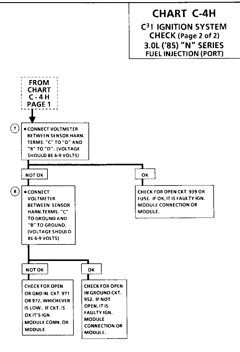
CHART C-4H C 3 I IGNITION SYSTEM CHECK (Page 2 of 2) 3.OL ('85) "N" SERIES
For timing of spark plug firing, a dual crankshaft sensor "hall effect" switch is used. The cam signal part of this switch sends a signal to the ignition module when cylinder #1 is on the compression stroke. This signal is used to start the correct sequence of coil firing. The engine will still run if the cam signal is lost while running, however, will not restart after shut down and a Code 41 will be stored if the cam signal was lost while running. The crankshaft sensor also sends a signal to the ignition module and then to the ECM for reference RPM and crankshaft position. There are three windows in a disc which is mounted to the harmonic balancer. These windows pass by the sensor and as each window passes, the next coil is triggered.
7. This voltage is supplied by the module and is pulled low by the sensor each time a window in a rotating disc is aligned with one of the "hall effect" switches. This results in a "crank" or "cam" signal as measured at the ignition module.
8. Checks to see if problem is in ground circuit 952, crank signal circuit 971, Cam signal circuit 972, or ignition module.
General Motors bulletins are intended for use by professional technicians, not a "do-it-yourselfer". They are written to inform those technicians of conditions that may occur on some vehicles, or to provide information that could assist in the proper service of a vehicle. Properly trained technicians have the equipment, tools, safety instructions and know-how to do a job properly and safely. If a condition is described, do not assume that the bulletin applies to your vehicle, or that your vehicle will have that condition. See a General Motors dealer servicing your brand of General Motors vehicle for information on whether your vehicle may benefit from the information.
