The air conditioning refrigerant (R-134a) recovery, recycling and recharging system (J 39500) removes and recharges with one hook-up.
Single-pass filtering during the recovery cycle, together with automatic multiple-pass filtering during the evacuation cycle, ensures a constant supply of clean/dry refrigerant for A/C system charging.
Important:
• R-12 and R-134a require separate sets of equipment for all operations.
The refrigerants and lubricants are not compatible. Do not mix the refrigerants,
even in the smallest amounts. Equipment always contains residue. Mixing refrigerant
residue will damage the equipment. • Adaptors which convert from one size fitting to the other must
never be used. Refrigerant/lubricant contamination will occur. This will cause
system failure.
Station (ACR4) Setup and Maintenance
Refer to the manufacturer's instructions for all initial setup procedures.
Caution: Use only authorized 23 kg (50 lb) refillable refrigerant tanks (J 39500-50). Using other tanks may cause personal injury. Using other tanks may void the warranty.
Connect the high side (Red) and the low side (Blue) hoses to the ACR4 unit. Route the hoses through the hose reel bracket grommets.
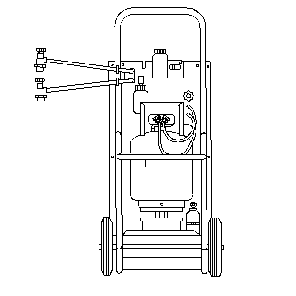
Notice: As per SAE specifications, the Refrigerant-134a systems have special fittings in order to avoid cross-contamination with the Refrigerant-12 systems. Do not adapt this unit to the Refrigerant-12 systems. Severe system failure will result.
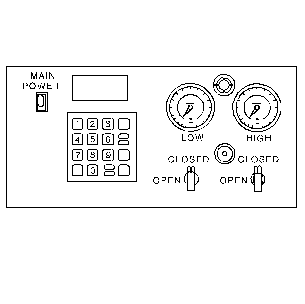
Control Panel Functions
This section explains the functions of the control panel.
| • | The Main Power Switch: The main power switch supplies electrical power to the control panel. |
| • | The Beeper: The beeper emits an audible tone to alert the operator to unit operating functions. |
| • | The Digital Display: The digital display shows the time programmed for vacuum. The display shows the weight of the refrigerant programmed for recharging. Detailed instructions for programming this display are included in digital display functions in this service category. |
| • | The Low Side Manifold Gage: This gage shows the system's low side pressure. |
| • | The High Side Manifold Gage: This gage shows the system's high side pressure. |
| • | The Moisture Indicator: This indicator shows if the refrigerant is wet or dry. |
| • | The Low Side Valve: This valve connects the low side of the A/C system to the unit. |
| • | The High Side Valve: This valve connects the high side of the A/C system to the unit. |
The Keypad
In addition to the number keys, the control panel contains special keys that accomplish specific operating functions.
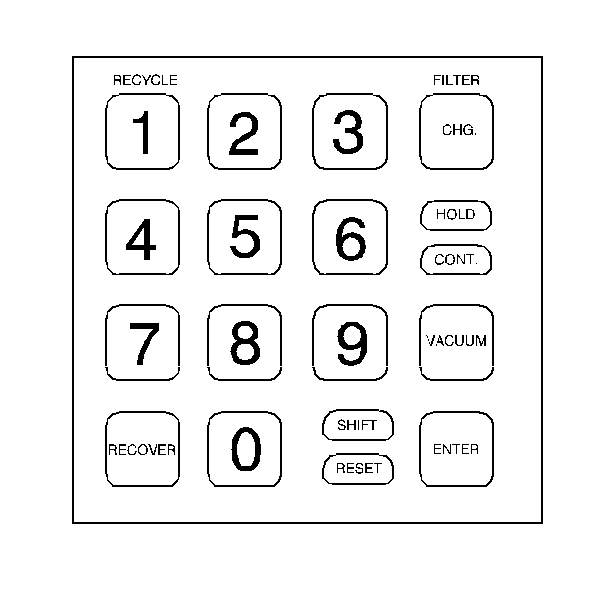
RECYCLE: Recycle activates the recycling sequence.
RECOVER: Recover activates the recovery sequence.
SHIFT/RESET: Shift/Reset activates shifted positions of the keys on the keypad and resets the program mode.
FILTER: Filter automatically recovers and evacuates to 17 in Hg. from the filter and the low side of the unit.
CHG: The CHG key automatically charges the A/C system with the programmed amount of refrigerant.
HOLD/CONT: Hold/Cont interrupts the automatic cycle in the HOLD position, then resumes functions in the CONT position. Press this button once for HOLD and again for CONT.
VACUUM: Vacuum activates the vacuum and automatic recycling sequence.
ENTER: The Enter key enters programmed data into the unit's control memory.
Digital Display Functions
For information regarding the functions of the digital display, refer to the manufacturer's instructions.
Maintenance
Refer to the manufacturer's instructions for all maintenance procedures.
