GM Service Manual Online
For 1990-2009 cars only

Base Brake System

The brake systems use conventional braking under normal operating conditions. The following components are necessary for operation of conventional braking:

    • The brake pedal force
    • The vacuum booster
    • The compact master cylinder

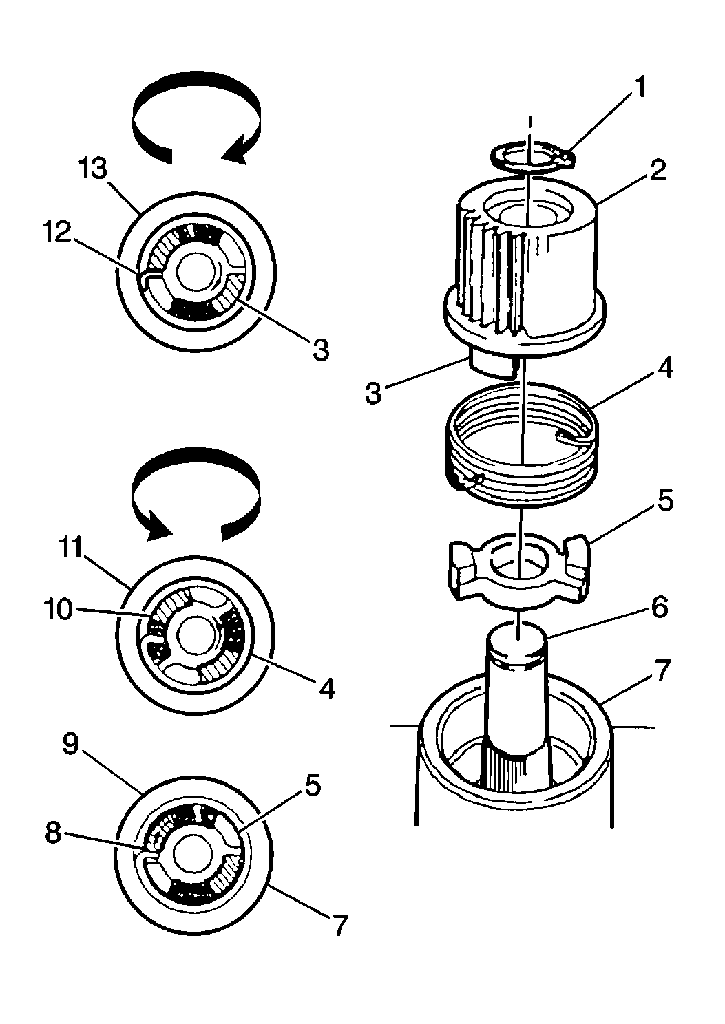
ABS Modulator Fluid Flow

Each front channel consists of the following components:

    • A motor
    • A solenoid
    • An ESB
    • A ball screw
    • A piston
    • A check valve

The following conditions exist under normal operating conditions (base brakes):

    • The piston remains in the highest (home) position.
    • The solenoid remains open (not energized).

The following actions permit the above conditions to exist:

    • The motor turns the ball screw upward, which then drives the nut upward.
    • The Expansion Spring Brake (ESB) holds the piston at the upmost position.

Antilock Brake System (ABS)

The ABS VI improves the controllability and the steerability of a vehicle during braking. The ABS VI improves the controllability and steerability by controlling the hydraulic pressure that applies to each wheel brake.

Antilock braking occurs when the following conditions exist:

    • The brake switch closes.
    • A microprocessor (which is located in the EBCM) determines that one or more of the wheels is about to lose traction during braking.

When the above conditions exist, the EBCM allows the ABS brake modulator to change the brake pressure several times per second.

The above action causes the following conditions:

    • The wheels cannot lock.
    • The driver has maximum vehicle control.

The ABS VI cannot perform the following actions:

    • Increase the brake pressure above the master cylinder pressure that the driver applies
    • Apply the brakes by itself

The ABS VI provides the following conditions:

    • Greatly improved braking that enables the driver to maintain steerabilty and to bring the vehicle to a controlled stop.
    • Effective braking and directional control over a wide range of road surfaces and braking conditions.

If any wheel(s) begin to approach lock-up, the EBCM will control the following components in order to control the brake pressure to the affected wheel(s):

    • The three motors
    • The two solenoids

During front wheel ABS operation, the solenoids turn on in order to isolate the brake pressure to the affected wheel(s).

The EBCM then provides controlled current to the motors in order to regulate the following items:

    • The speed
    • The amount of movement

The following actions occur when the EBCM provides controlled current:

    • As the motors move backward, the piston follows the nut downward.
        The above condition permits seating of the check valve.
        The brake pressure to the wheel becomes a function of the controlled volume within the piston chamber.
    • The motor drives the nut further downward in order to reduce brake pressure.
    • The motor drives the nut and the piston upward in order to reapply or increase pressure.

If ABS was entered during low brake pressure (such as on ice) and a dry surface is encountered during the reapply action, the piston drives all of the way to the top. Driving the piston to the top position causes the following conditions:

    • The check valve unseats.
    • The system returns to base brakes.
        Base brakes will be used until the brake pressure is high enough to cause the wheel to approach lock-up again. Then the ABS cycle will start again.
        The above process may occur in less than one second if the driver presses firmly on the brake pedal.

The total brake pressure during ABS must not exceed the brake pressure that was present when ABS was entered.

Reduced pressure on the brake pedal may cause the wheel brake pressure to exceed the brake pressure at the master cylinder. The following actions result when the above condition occurs:

    • The check valve unseats
    • A small amount of brake fluid is returns to the master cylinder.

The ABS VI cannot increase the brake pressure above the master cylinder pressure that the driver applies.

The ABS VI cannot apply the brakes by itself.

The following actions occur when the ABS is no longer required:

    • The pistons return to their upmost (home) position.
    • The ESBs hold the pistons in place.
        Refer to ESB Operation.
    • The solenoids on the front channels simultaneously open. Simultaneous opening of the solenoids provides a redundant braking path.

The operation of the rear channel is similar to operation of the front channels except for the following actions that exist in the rear channel:

    • No solenoid is used.
    • The same motor controls the pressure of both rear brakes.
    • The rear brake pressures are controlled together.
        If either of the rear wheels begins to lock, brake pressure to both wheels reduces. Reduced brake pressure maximizes vehicle stability.

No rear solenoid exists. The front brakes perform most of the braking.

If an ABS failure that affects the operation of the rear base brake occurs, the following actions will occur:

    • A diagnostic trouble code will store.
    • The EBCM will turn on the ABS warning indicator.

ESB Operation


Object Number: 155184  Size: MH
(1)Circlip
(2)Motor Pinon
(3)Pinion Drive Dog
(3)Pinion Drive Dog
(4)Expansion Spring Brake (ESB)
(5)Motor Drive Dog
(5)Motor Drive Dog
(6)Motor Shaft
(7)Steel Sleeve
(8)Pinion Dog Expands Springs and Locks Against Sleeve
(9)Pinion Stopped From Turning Clockwise
(10)Motor Drive Dog Releases Spring Brake (Spring Leg Beneath Pinion Dog And Drives Pinion)
(11)Motor Drives Counter Clockwise
(12)Motor Drive Dog Releases
(13)Motor Drives Clockwise

The Expansion Spring Brake (ESB) holds the piston in the upmost (home) position of the piston.

An ESB is a spring that is retained in a housing at a close tolerance. One end of the spring touches the motor drive dog. The other end of the spring touches the pinion drive dog.

During normal braking, brake pressure exists at the top of the piston. The pressure applies a downward force. The downward force applies a counterclockwise torque to the motor pinion. The motor pinion tries to rotate the spring counterclockwise. The counterclockwise torque expands the spring outward within the housing. Outward expansion of the spring within the housing prevents gear rotation.

The following actions occur when the motor is on and tries to drive the ball screw nut:

    • The end of the ESB that touches the motor drive dog rotates inward.
    • The spring contracts in the spring housing.
    • The motor rotates the modulator gear.

The most common application of this principle is in window crank mechanisms. A small amount of force on the crank handle will cause the window to move upward or downward, but the weight of the window (or any pressure on the window) does not cause the window to move downward. In the ESB, the brake pressure at the top of the pistons corresponds to the weight of the window. The motor corresponds to the window crank handle.

System -- Self Test (Initialization)

The EBCM performs self-diagnostics during initialization.

The EBCM also verifies correct operation of the following components during initialization:

    • The motor
    • The modulator
    • The solenoid
    • The relay
    • The indicators

The EBCM inspects the wheel speed sensor circuitry for the following conditions during initialization:

    • Open circuits
    • Shorts to the ground
    • Shorts to voltage

If the EBCM detects a malfunction in itself or in other ABS VI components, the EBCM will perform the following actions:

    • Stores a Diagnostic Trouble Code (DTC)
    • Turns on one or more of the following indicators, if applicable:
       - The amber ABS warning indicator
       - The red BRAKE warning indicator

The following indicators will remain on for approximately three seconds with the key in the RUN position:

    • The amber ABS warning indicator
    • The red BRAKE warning indicator

The following indicators will turn on during cranking and remain on for approximately three seconds after the engine starts:

    • The amber ABS warning indicator
    • The red BRAKE warning indicator

The initialization performs during engine cranking and engine starting. A slight mechanical noise may be heard during the system initialization. This noise is normal.

If the brake pedal depresses when the engine starts, the system will not initialize. The system will initialize when one of the following actions occurs:

    • The pressure leaves the brake pedal
    • The vehicle attains a speed of 5 km/h (3 mph).

If brake pedal pressure interrupts the system initialization, a slight movement in the brake pedal may exist.

Normal/Indicator System Operation

The standard brake system uses a single red BRAKE warning indicator, which is located in the instrument panel cluster.

The antilock brake system uses the following indicators:

    • The red BRAKE warning indicator
    • An amber ABS warning indicator

The following indicators will turn on for approximately three seconds and then turn off when the ignition is turned to the RUN position:

    • The amber ABS warning indicator
    • The red BRAKE warning indicator

The amber ABS indicator lamp will be illuminated to alert the driver of a malfunction. This indicates that the malfunction affects operation of ABS. Normal (non-antilock) braking will remain. In order to regain ABS braking ability, the ABS must be serviced.

The red BRAKE warning lamp will illuminate when the park brake is set (direct input to IPC) or when the brake fluid level switch within the master cylinder reservoir drops below a safe level (commanded by the EBCM via serial data link).

Tires and ABS

Spare Tire

Using the compact spare supplied with the vehicle will not affect the operation of ABS. The EBCM software can compensate for this smaller tire. However, increased stopping distances may occur due to reduced tire tread depth on compact spare tires.

Replacement Tires

Tire size is important for proper performance of the ABS. Replacement tires should be the same size, load range, and construction as the original tires. Replace tires in axle sets and only with tires of the same Tire Performance Criteria (TPC) specification number. Use of any other tire size or type may seriously affect the ABS operation.