Intake Manifold Cleaning and Inspection Upper VIN M
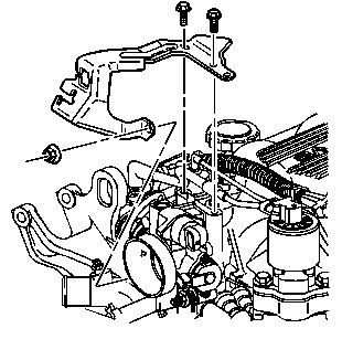
- Remove the accelerator control cable bracket bolts and nut.
- Remove the accelerator control cable bracket.
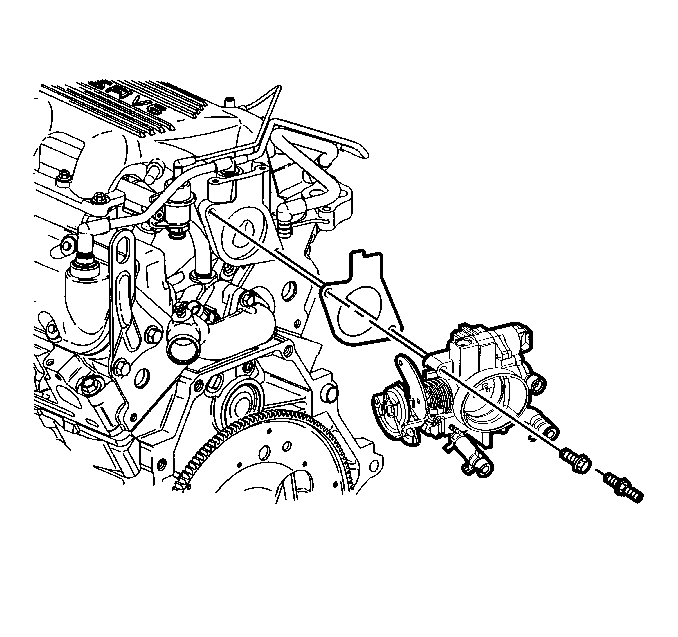
- Remove the throttle body bolt and stud.
- Remove the throttle body.
- Remove the throttle body gasket.
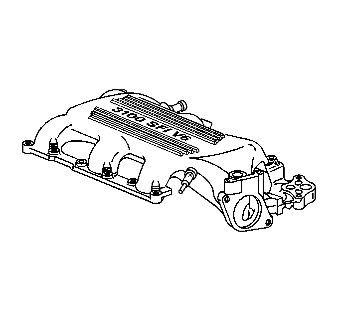
- Clean the intake manifold gasket surfaces.
- Clean the intake manifold bolts and studs.
- Inspect the intake manifold mating surfaces for nicks or cracks.
- Replace the intake manifold if damaged.
- Install the throttle body gasket.
- Install the throttle body.
- Install the throttle body bolt and stud.
- Install the accelerator control cable bracket.
- Install the accelerator control cable bracket bolts and nut.

Notice: Use the correct fastener in the correct location. Replacement fasteners must be the correct part number for that application. Fasteners requiring replacement or fasteners requiring the use of thread locking compound or sealant are identified in the service procedure. Do not use paints, lubricants, or corrosion inhibitors on fasteners or fastener joint surfaces unless specified. These coatings affect fastener torque and joint clamping force and may damage the fastener. Use the correct tightening sequence and specifications when installing fasteners in order to avoid damage to parts and systems.
Tighten
Tighten the throttle body bolt and stud to 25 N·m (18 lb ft).
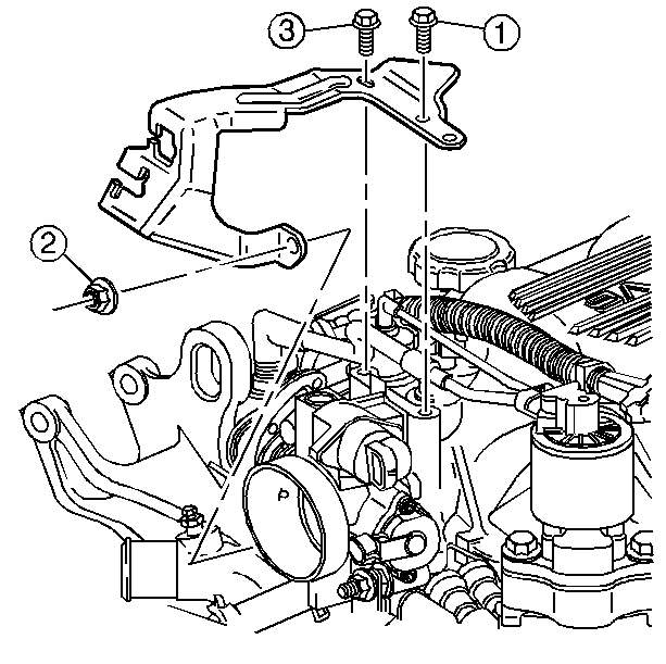
Tighten
Tighten the accelerator control cable bracket bolts and nut in sequence
(1, 3, 2) to 10 N·m (89 lb in).
Intake Manifold Cleaning and Inspection Lower
Tools Required
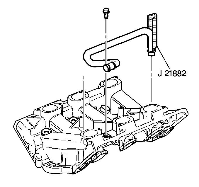
J 21882 Oil Suction Pipe Installer
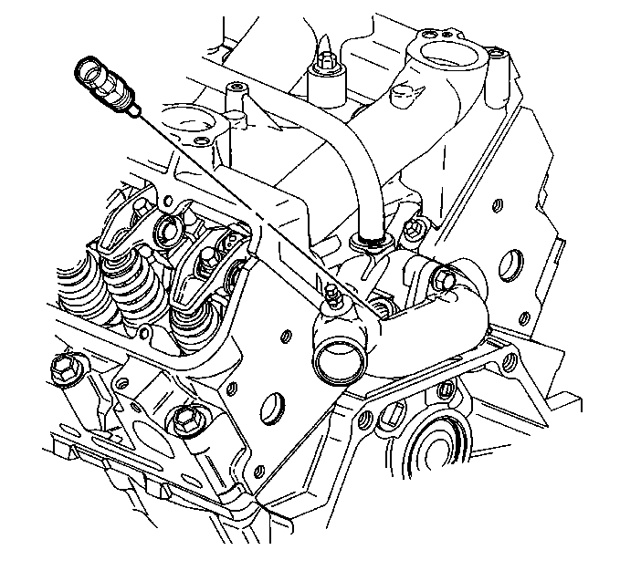
- Remove the engine coolant temperature sensor.
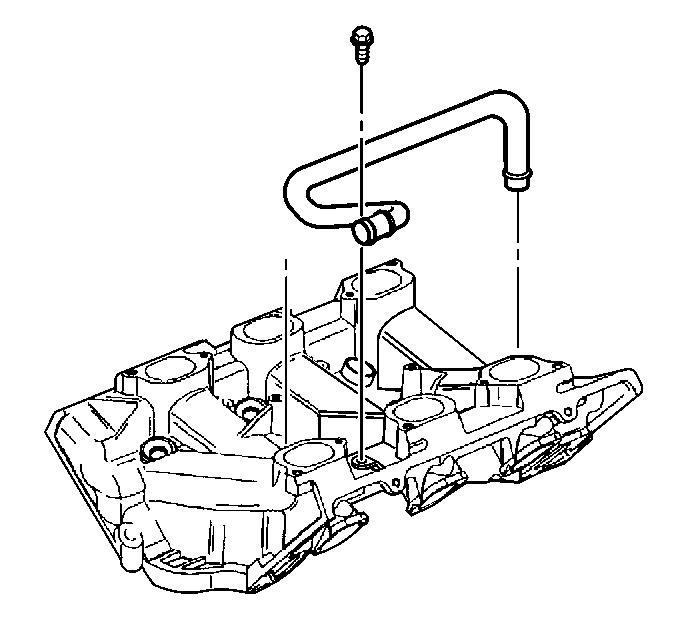
- Remove the intake manifold coolant pipe bolt.
- Remove the intake manifold coolant pipe.
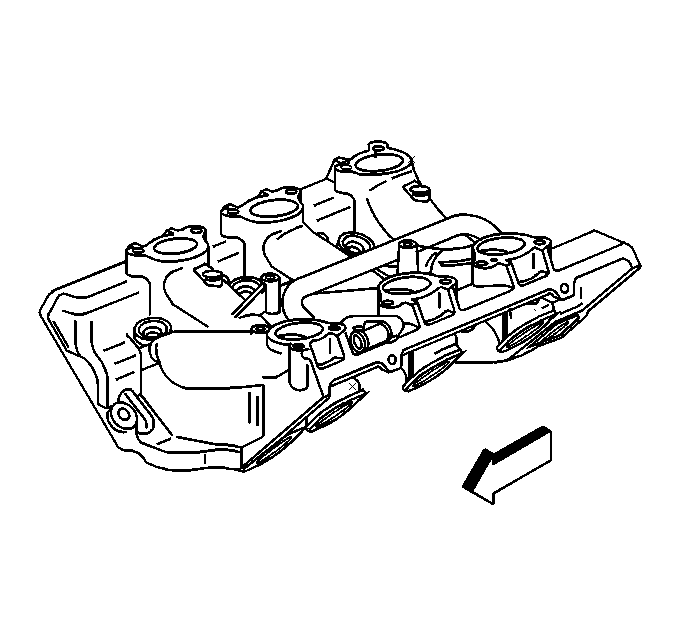
- Clean the intake manifold gasket mating surfaces.
- Clean the fuel injector bores.
- Inspect the threaded holes for damage.
- Inspect the intake manifold mating surfaces for damage.
- Repair or replace the intake manifold as necessary.
- Apply sealant GM P/N 12345493 or equivalent to the end of a new intake manifold coolant pipe.
- Install the intake manifold coolant pipe using the J 21882 .
- Install the intake manifold coolant pipe bolt.
- Install the engine coolant temperature sensor. Apply sealer GM P/N 12346004 or equivalent to the coolant temperature sensor.
Notice: Use the correct fastener in the correct location. Replacement fasteners must be the correct part number for that application. Fasteners requiring replacement or fasteners requiring the use of thread locking compound or sealant are identified in the service procedure. Do not use paints, lubricants, or corrosion inhibitors on fasteners or fastener joint surfaces unless specified. These coatings affect fastener torque and joint clamping force and may damage the fastener. Use the correct tightening sequence and specifications when installing fasteners in order to avoid damage to parts and systems.
Tighten
Tighten the intake manifold coolant pipe bolt to 10 N·m
(89 lb in).

Tighten
Tighten the engine coolant temperature sensor to 23 N·m
(17 lb ft).
