For 1990-2009 cars only
Circuit Description
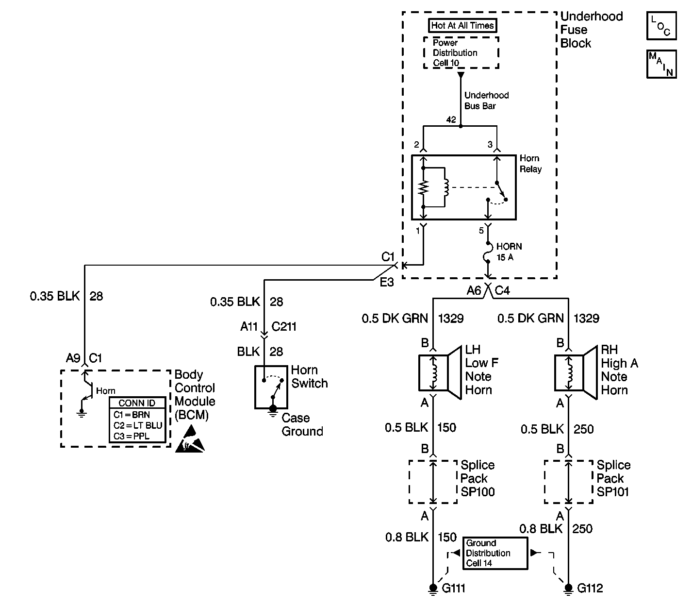
CKT 28 is an input to the BCM. The BCM monitors CKT 28 in order to determine if the horn circuit is shorted to ground.
Conditions for Setting the DTC
| • | When CKT 28 is shorted to ground for more than 184 seconds. |
| • | The system voltage is between 9.0-16.0 volts. |
| • | The above conditions exist for 184 seconds. |
Action Taken When the DTC Sets
The horn will remain ON at all times.
Conditions for Clearing the MIL/DTC
| • | A current DTC will clear after the next ignition cycle that does not contain a fault. |
| • | A history DTC will clear after 100 consecutive ignition cycles without a fault present. |
| • | History and current DTCs may be cleared using a scan tool. |
Diagnostic Aids
| • | Always diagnose the first DTC that is listed on the scan tool. |
| • | Verify that the scan tool displays DTC B2752 as a current code before you perform diagnostics. |
| • | Determine if the horn pad or the horn switch sticks. |
| • | Inspect for loose or poor connections at all of the related components. |
| • | Refer to Intermittents and Poor Connections Diagnosis in Wiring Systems. |
Test Description
The number below refers to the step number on the diagnostic table.
Step | Action | Value(s) | Yes | No | ||||||
|---|---|---|---|---|---|---|---|---|---|---|
1 | Did you perform the BCM Diagnostic System Check? | -- | Go to Step 2 | |||||||
Does the test lamp light? | -- | Go to Step 3 | Go to Step 4 | |||||||
3 | Locate and repair the short to ground in CKT 28 (BLK) between the following components:
Is the repair complete? | -- | Go to Step 5 | -- | ||||||
4 |
Is the repair complete? | -- | Go to Step 5 | -- | ||||||
5 | Clear the DTCs. Is the repair complete? | -- | -- |
