Removal Procedure
- Relieve the fuel system pressure. Refer to the Fuel Pressure Relief .
- Drain the fuel tank. Refer to Fuel Tank Draining .
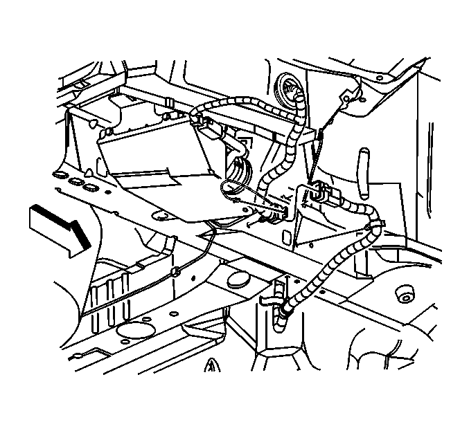
- Raise the vehicle. Refer to Lifting and Jacking the Vehicle in General Information.
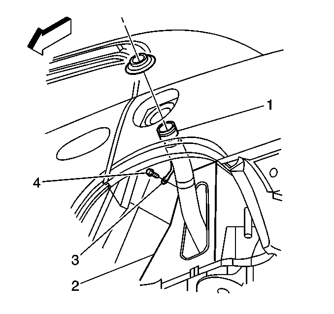
- Remove the wheel house filler pipe opening cover (2).
- Disconnect the fuel fill hose from the fuel fill pipe.
- Remove the rear suspension support assembly. Refer to Support Replacement in Rear Suspension.
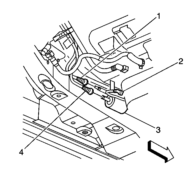
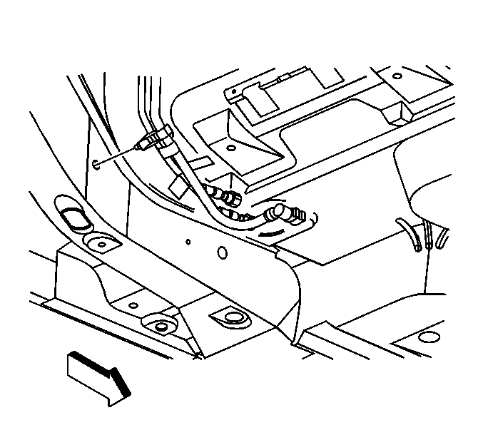
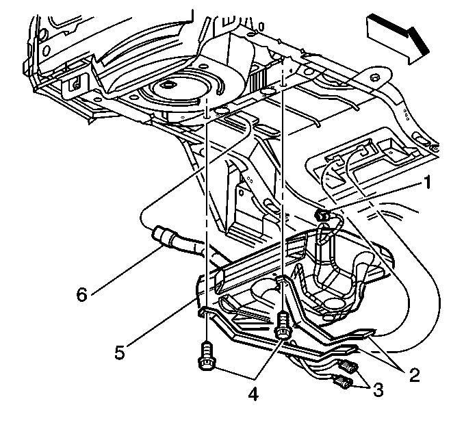
- Disconnect the fuel feed pipe (4) and the fuel return pipe (1). Refer to Plastic Collar Quick Connect Fitting Service .
- Disconnect the EVAP pipe (2) from the EVAP canister.
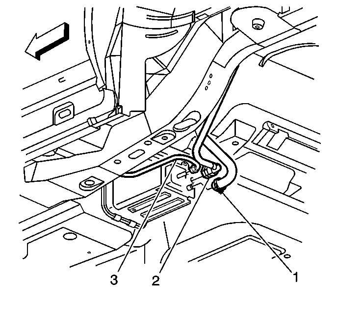
- Remove the fuel and EVAP retainer from the frame.
- Disconnect the fuel tank electrical connector.
- Disconnect the fuel tank electrical harness from the retainers.
- Remove the fuel tank strap bolts (4).
- Remove the fuel tank (5).
Disassemble Procedure
- If the fuel tank is not being replaced refer to the Installation Procedure.
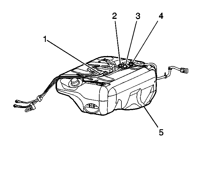
- Remove the fuel pipes (2, 3) and the EVAP pipe (1).
- Remove the fuel sender assembly. Refer to Fuel Sender Assembly Replacement .
- Remove the fuel filler hose clamp (2).
- Remove the fuel filler hose from the fuel tank (3).
Assemble Procedure
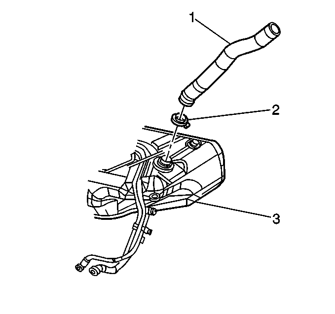
- Install the fuel filler hose to the fuel tank (3). Align the dot on the hose to the parting line on the fuel tank.
- Install the fuel filler hose clamp (2).
- Install the fuel sender assembly. Refer to Fuel Sender Assembly Replacement .
- Install the fuel pipes (2, 3) and the EVAP pipe (1).
Notice: Use the correct fastener in the correct location. Replacement fasteners must be the correct part number for that application. Fasteners requiring replacement or fasteners requiring the use of thread locking compound or sealant are identified in the service procedure. Do not use paints, lubricants, or corrosion inhibitors on fasteners or fastener joint surfaces unless specified. These coatings affect fastener torque and joint clamping force and may damage the fastener. Use the correct tightening sequence and specifications when installing fasteners in order to avoid damage to parts and systems.
Tighten
Tighten the clamp to 3.5 N·m (31 lb in).
Installation Procedure
- Position and support the fuel tank (5) with the aid of an assistant.
- Install the fuel tank straps (2).
- Install the fuel tank strap bolts (4).
- Connect the fuel tank electrical connector.
- Install the fuel tank electrical harness into the retainers.
- Install the fuel and EVAP retainer to the frame.
- Connect the EVAP pipe (2) to the EVAP canister.
- Connect the fuel feed pipe (4) and the fuel return pipe (1). Refer to Plastic Collar Quick Connect Fitting Service .
- Install the rear suspension support assembly. Refer to Support Replacement in Rear Suspension.
- Connect the fuel filler hose to the fuel filler pipe.
- Install the wheelhouse filler pipe opening cover (2).
- Lower the vehicle.
- Add fuel to the fuel tank.
- Install the fuel tank filler pipe cap.
- Connect the negative battery cable. Refer to Battery Negative Cable Disconnection and Connection in Engine Electrical.
- Inspect for leaks.
- Install the fuel injector sight shield. Refer to Fuel Injector Sight Shield Replacement in Engine Mechanical-4.0L.
Notice: Use the correct fastener in the correct location. Replacement fasteners must be the correct part number for that application. Fasteners requiring replacement or fasteners requiring the use of thread locking compound or sealant are identified in the service procedure. Do not use paints, lubricants, or corrosion inhibitors on fasteners or fastener joint surfaces unless specified. These coatings affect fastener torque and joint clamping force and may damage the fastener. Use the correct tightening sequence and specifications when installing fasteners in order to avoid damage to parts and systems.
Tighten
Tighten the fuel tank strap bolts to 42 N·m (31 lb ft).
Tighten
Tighten the clamp to 3.5 N·m (31 lb in).
| 16.1. | Turn ON the ignition, with the engine OFF for 2 seconds. |
| 16.2. | Turn OFF the ignition for 10 seconds. |
| 16.3. | Turn ON the ignition, with the engine OFF. |
| 16.4. | Inspect for fuel leaks. |
