- Remove the left instrument
panel insulator. Refer to
Instrument Panel Insulator Panel Replacement - Left Side
in Instrument Panel, Gauges and Console.
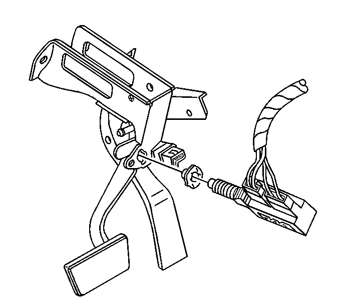
- Disconnect the wiring harness connectors from the brake release
switch.
- Pull the brake release switch rearward in order to remove the
switch from the retainer.
Installation Procedure
- Install the brake release
switch retainer into the bracket, from the forward side.
- With the brake pedal depressed, insert the switch into the retainer
until the switch seats on the retainer. You may hear audible clicks as the
ribbed portion of the switch pushes forward through the retainer.
- Connect the wiring harness connectors to the brake release switch.
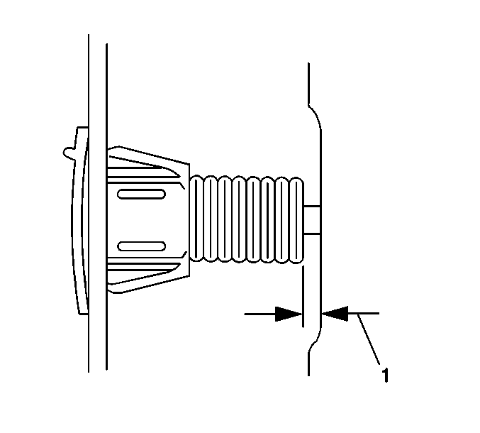
- Adjust the brake release
switch using the following procedure:
| 4.1. | Pull the brake pedal fully rearward against the pedal stop until
you can not hear audible clicks. The brake release switch moves in the retainer.
This movement provides adjustment. |
| 4.2. | Release the brake pedal. |
| 4.3. | Repeat these steps in order to ensure that you have
properly adjusted the switch. |
- Install the left instrument panel insulator. Refer to
Instrument Panel Insulator Panel Replacement - Left Side
in Instrument Panel,
Gauges and Console.
