Engine Replacement Manual Transmission
Removal Procedure
- Disconnect the negative battery cable. Refer to
Battery Negative Cable Disconnection and Connection
in Engine
Electrical.
- Drain the cooling system. Refer to
Cooling System Draining and Filling
in Engine Cooling.
- Evacuate the A/C System. Refer to
Refrigerant Recovery and Recharging
in Heating, Ventilating, and
Air Conditioning.
- Remove the air cleaner duct. Refer to
Air Cleaner Inlet Duct Replacement
in Engine Controls-2.4L.
- Remove the air cleaner. Refer to
Air Cleaner Assembly Replacement
in Engine Controls-2.4L.
- Remove the underhood fuse block.
- Remove the air cleaner bracket. Refer to
Air Cleaner Bracket Replacement
in Body Front End.
- Disconnect the shift cables
at the shift control.
- Remove the shift cables
from the bracket and remove the bracket.
- Disconnect the back up
lamp switch.
- Disconnect the vehicle
speed sensor.
- Disconnect the upper engine electrical harness. Refer to
Harness Routing Views
in Engine Controls.
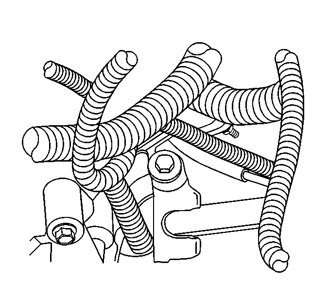
- Disconnect the vacuum lines. Refer to
Emission Hose Routing Diagram
in Engine Controls.
- Relieve the fuel pressure. Refer to
Fuel Pressure Relief
in Engine Controls.
- Disconnect the fuel line quick disconnects. Refer to
Metal Collar Quick Connect Fitting Service
in
Engine Controls.
- Remove the upper radiator hose. Refer to
Radiator Hose Replacement
in Engine Cooling.
- Disconnect the heater hoses from the heater core. Refer to
Heater Hoses Replacement
in Heating, Ventilating
and Air Conditioning.
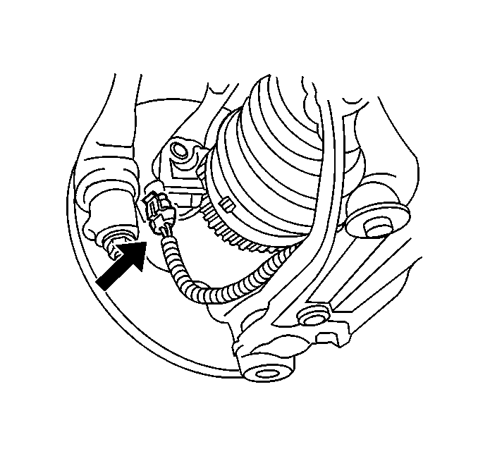
- Disconnect the slave cylinder
hydraulic line.
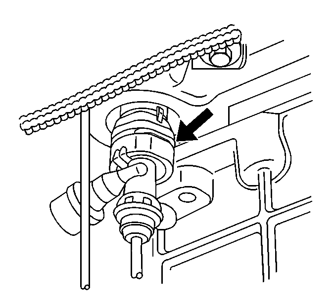
- Remove the EVAP solenoid.
- Disconnect the ground cables at the rear of the engine block.
Refer to
Harness Routing Views
in Engine
Electrical.
- Remove the power steering pump with lines attached and position
the pump out of the way. Refer to
Power Steering Pump Replacement
in Power Steering Systems.
- Disconnect the electrical connector from the A/C compressor and
the CKP. Position the harness aside.
- Remove the starter with the wires attached and position it out
of the way. Refer to
Starter Motor Replacement
in Engine Electrical.
- Disconnect the surge tank bypass hose from the engine. Refer to
Radiator Surge Tank Replacement
in Engine Cooling.
- Disconnect the cruise and accelerator cables from the throttle
body. Refer to
Accelerator Control Cable Replacement
in Engine Controls.
- Remove and position aside the cruise control module. Refer to
Cruise Control Module Replacement
in Cruise Control.
- Tie the radiator to the hood latch panel with mechanics wire.
- Raise and support the vehicle. Refer to
Lifting and Jacking the Vehicle
in General Information.
- Safety strap the front of the vehicle to the hoist.
- Drain the transaxle.
- Drain the engine oil and remove the oil filter. Refer to
Engine Oil and Oil Filter Replacement
.
- Remove the engine splash shields. Refer to
Engine Splash Shield Replacement
in Body Front End.
- Remove the front closeout panel fasteners and the panel.
- Remove the lower radiator support. Refer to
Radiator Support Replacement
in Collision Repair.
- Remove the right front brake hose from the vehicle. Refer to
Front Brake Hose Replacement
in Hydraulic Brakes.
- Remove the retaining nut from the BPMV at the mounting bracket.
- Disconnect the wheel speed
sensors.
- Remove the wheel speed
sensor harnesses from the control arm retainers.
- Remove the wheel speed
sensor harnesses from the frame retainers and position them out of the way.
- Remove the wheel driveshafts. Refer to
Wheel Drive Shaft Replacement
in Wheel Drive Shafts.
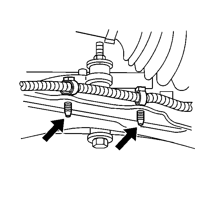
- Disconnect the ball joints from the control arms. Refer to
Lower Control Arm Ball Joint Replacement
in Front Suspension.
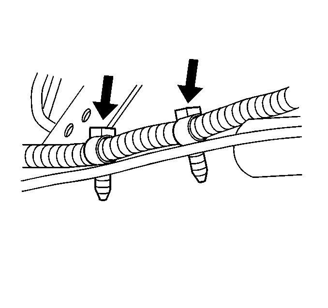
- Disconnect the outer tie rod ends from the control arms. Refer
to
Rack and Pinion Outer Tie Rod End Replacement
in Steering.
- Disconnect the catalytic converter from the exhaust manifold.
Refer to
Catalytic Converter Replacement
in Engine Exhaust.
- Remove the A/C compressor hose from the A/C compressor. Refer
to
Compressor Hose Assembly Replacement
in Heating, Ventilating, and Air Conditioning.
- Remove the bolt from the power steering pressure line retainer.
Refer to
Power Steering Pressure Pipe/Hose Replacement
in Power Steering Systems.
- Lower the vehicle until the front suspension crossmember rests
on the support table.
- Position a three inch block of wood between the front of the oil
pan and the crossmember.
- Remove the front engine mount to bracket bolts. Refer to
Engine Mount Replacement
.
- Remove the front suspension crossmember retaining bolts. Refer
to
Front Suspension Crossmember Replacement
in Front Suspension.
- With the help of an assistant, carefully raise the vehicle off
of the engine/transaxle assembly.
- Install the engine hoist to the engine/transmission assembly.
- Remove the front transmission
mount thrubolt.
- Remove the rear transmission
mount thrubolt.
- Remove the two side transmission
mount lower nuts.
- Lift the engine/transaxle assembly off of the front suspension
crossmember.
- Separate the transaxle from the engine. Refer to
Transmission Replacement
.
- Remove the clutch drive plate and clutch driven plate.
- Remove the flywheel. Refer to
Engine Flywheel Replacement
.
- Mount the engine on a suitable engine stand.
Installation Procedure
- Remove the engine from the engine stand.
- Install the flywheel to the engine. Refer to
Engine Flywheel Replacement
.
- Install the clutch driven plate and clutch drive plate.
- Install the transaxle to the engine.
- Lower the engine/transaxle assembly on to the front suspension
crossmember.
Notice: Use the correct fastener in the correct location. Replacement fasteners
must be the correct part number for that application. Fasteners requiring
replacement or fasteners requiring the use of thread locking compound or sealant
are identified in the service procedure. Do not use paints, lubricants, or
corrosion inhibitors on fasteners or fastener joint surfaces unless specified.
These coatings affect fastener torque and joint clamping force and may damage
the fastener. Use the correct tightening sequence and specifications when
installing fasteners in order to avoid damage to parts and systems.
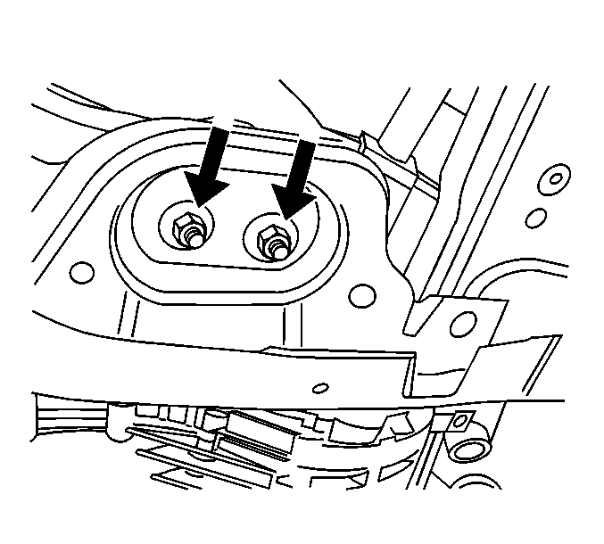
- Install the two
side transmission mount lower nuts.
Tighten
Tighten the transmission mount lower nuts to 44 N·m (60 lb ft).
- Install the rear transmission
mount thrubolt.
Tighten
Tighten the rear transmission mount thrubolt to 55 N·m
(75 lb ft).
- Install the front transmission
mount thrubolt.
Tighten
Tighten the front transmission thrubolt to 55 N·m (75 lb ft).
- Remove the engine hoist from the engine/transaxle assembly.
- With the help of an assistant, carefully lower the vehicle on
to the engine/transaxle assembly.
- Install the front suspension crossmember retaining bolts Refer
to
Front Suspension Crossmember Replacement
in Front Suspension.
- Install the front engine mount to bracket bolts. Refer to
Engine Mount Replacement
.
- Raise the vehicle off of the support table.
- Install the bolt to the power steering pressure line retainer.
Refer to
Power Steering Pressure Pipe/Hose Replacement
in Power Steering Systems.
- Install the A/C compressor hose to the A/C compressor. Refer to
Compressor Hose Assembly Replacement
in Heating,
Ventilating, and Air Conditioning.
- Connect the catalytic converter to the exhaust manifold. Refer
to
Catalytic Converter Replacement
in Engine Exhaust.
- Connect the outer tie rod ends to the control arms. Refer to
Rack and Pinion Outer Tie Rod End Replacement
in Steering.
- Connect the ball joints to the control arms. Refer to
Lower Control Arm Ball Joint Replacement
in Front Suspension.
- Install the wheel driveshafts. Refer to
Wheel Drive Shaft Replacement
in Wheel Drive Shafts.
- Install the wheel speed
sensor harnesses to the frame retainers. Ensure the retainers lock into position.
- Install the wheel speed
sensor harnesses to the control arm retainers. Ensure that the retainers lock
into position.
- Connect the wheel speed
sensors.
- Install the retaining nut to the BPMV at the mounting bracket.
- Install the right front brake hose to the vehicle. Refer to
Front Brake Hose Replacement
in Hydraulic Brakes.
- Install the lower radiator support. Refer to
Radiator Support Replacement
in Collision Repair.
- Install the front closeout panel and the panel fasteners. Ensure
the fasteners are retained.
- Install the engine splash shields. Refer to
Engine Splash Shield Replacement
in Body Front End.
- Install a new oil filter and fill the engine with oil. Refer to
Engine Oil and Oil Filter Replacement
.
- Fill the transaxle with specified lubricant.
- Remove the safety straps from the front of the vehicle and the
hoist.
- Lower the vehicle.
- Untie the radiator from the hood latch panel.
- Install the cruise control module. Refer to
Cruise Control Module Replacement
in Cruise Control.
- Connect the cruise and accelerator cables to the throttle body.
Refer to
Accelerator Control Cable Replacement
in Engine Controls.
- Connect the surge tank bypass hose to the engine. Refer to
Radiator Surge Tank Replacement
in Engine Cooling.
- Install the starter. Refer to
Starter Motor Replacement
in Engine Electrical.
- Connect the electrical connectors to the A/C compressor and the
CKP.
- Install the power steering pump. Refer to
Power Steering Pump Replacement
in Power Steering Systems.
- Connect the ground cables at the rear of the engine block. Refer
to
Harness Routing Views
in Engine
Electrical.
- Install the EVAP solenoid. Refer to
Evaporative Emission Canister Purge Solenoid Valve Replacement
in
Engine Controls.
- Connect the slave cylinder
hydraulic line.
- Connect the heater hoses to the heater core. Refer to
Heater Hoses Replacement
in Heating, Ventilating,
and Air Conditioning.
- Connect the radiator hoses. Refer to
Radiator Hose Replacement
in Engine Cooling.
- Connect the fuel line quick disconnects. Refer to
Metal Collar Quick Connect Fitting Service
in Engine Controls.
- Connect the vacuum lines. Refer to
Emission Hose Routing Diagram
in Engine Controls.
- Connect the upper engine electrical harness. Refer to
Harness Routing Views
in Engine Controls.
- Connect the VSS.
- Connect the back up lamp
switch.
- Install the shift cable
bracket and the shift cables to the bracket.
- Connect the shift cables
at the shift control.
- Install the air cleaner bracket. Refer to
Air Cleaner Bracket Replacement
in Body Front End.
- Install the underhood fuse block.
- Install the air cleaner. Refer to
Air Cleaner Assembly Replacement
in Engine Controls.
- Install the air cleaner duct. Refer to
Air Cleaner Inlet Duct Replacement
in Engine Controls.
- Charge the A/C system. Refer to
Refrigerant Recovery and Recharging
in Heating, Ventilating, and Air Conditioning.
- Fill the cooling system. Refer to
Cooling System Draining and Filling
in Engine Cooling.
- Connect the negative battery cable. Refer to
Battery Negative Cable Disconnection and Connection
in Engine Electrical.
Engine Replacement Automatic Transmission
Tools Required
Removal Procedure
- Drain the engine coolant. Refer to
Cooling System Draining and Filling
in Engine Cooling.
- Drain the engine oil. Refer to
Engine Oil and Oil Filter Replacement
.
- Remove the fuel rail assembly. Refer to
Fuel Injection Fuel Rail Assembly Replacement
in Engine Controls-2.4L.
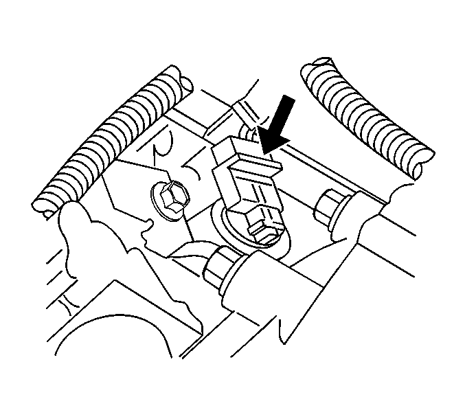
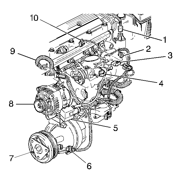
- Disconnect the ignition coil and the module assembly.
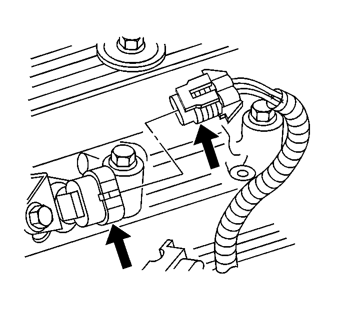
- Disconnect the camshaft
position sensor.
- Remove the power steering
pump and set aside with the lines attached.
- Disconnect the oil pressure
sending switch.
- Remove the cruise control module and set aside. Refer to
Cruise Control Module Replacement
in Cruise Control.
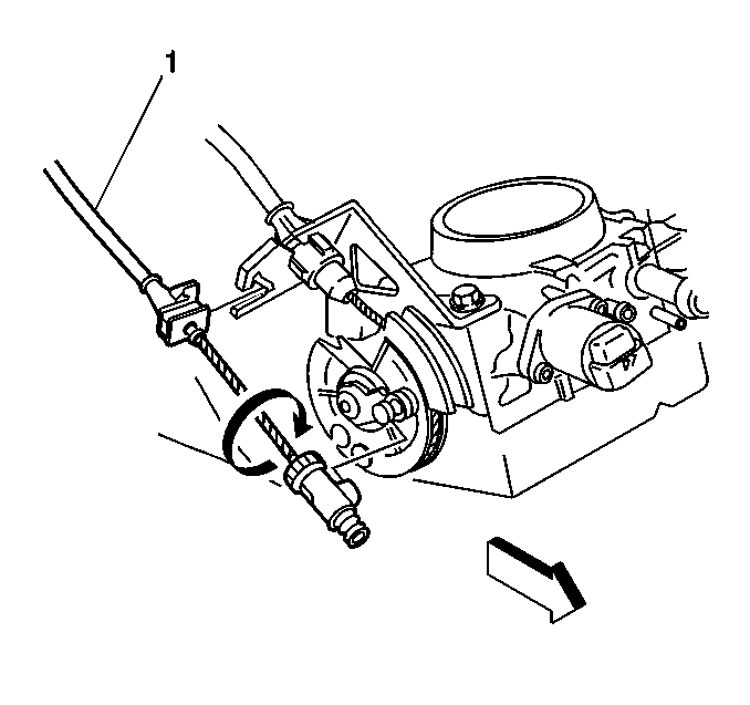
Caution: In order to avoid possible injury or vehicle damage, always replace
the accelerator control cable with a NEW cable whenever you remove the engine
from the vehicle.
In order to avoid cruise control cable damage, position the cable out
of the way while you remove or install the engine. Do not pry
or lean against the cruise control cable and do not kink the cable. You must
replace a damaged cable.
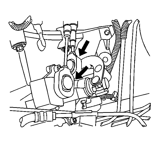
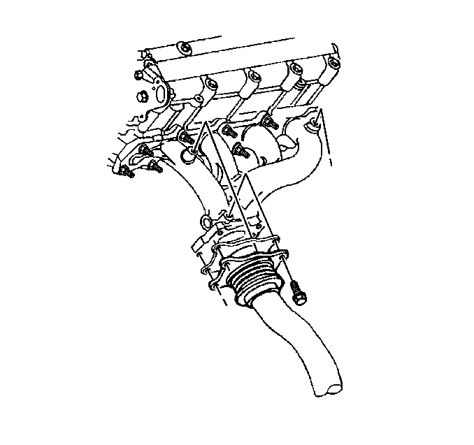
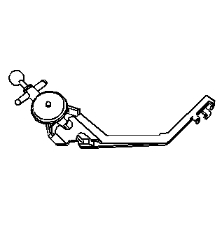
- Remove cruise (1) and throttle cables from throttle body.
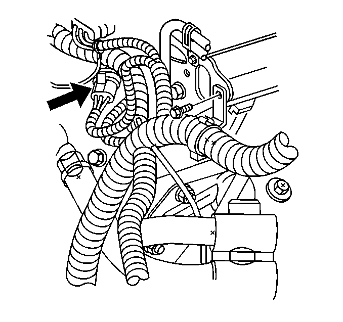
- Disconnect the following components:
| • | Vacuum line from throttle body |
| • | Disconnect TPS sensor (2). |
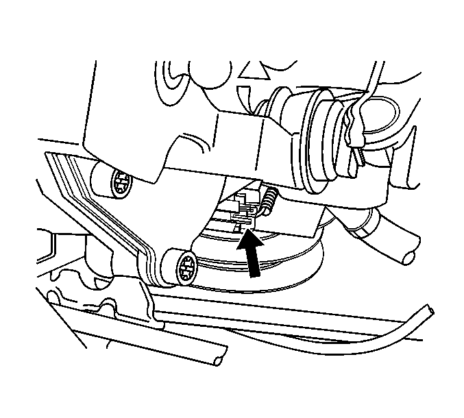
- Disconnect generator electrical.
- Remove brake booster line from engine.
- Remove surge tank hose from engine.
- Raise and suitably support the vehicle. Refer to
Lifting and Jacking the Vehicle
in General Information.
- Remove the drive belt. Refer to
Drive Belt Replacement
.
- Remove the crankshaft balancer. Refer to
Crankshaft Balancer Replacement
.
- Remove the starter. Refer to
Starter Motor Replacement
in Engine Electrical.
- Disconnect the exhaust
pipe from the exhaust manifold.
- Remove the torque converter bolts. Refer to
Transmission Replacement
in Automatic Transaxle-4T40-E/4T45-E.
- Remove the A/C compressor bolts. Position the compressor out of
the way. Refer to
Air Conditioning Compressor Replacement
in HVAC.
- Remove the lower oil pan to bell housing bolts.
- Remove lower radiator hose from engine.
- Lower the vehicle. Refer to
Lifting and Jacking the Vehicle
in General Information.
- Remove the transmission mount. Refer to
Transmission Mount Replacement - Side
in Automatic Transaxle-4T40-E/4T45-E.
- Remove upper radiator hose from engine.
- Remove the upper transmission to engine bolts.
- Install the engine lifting device. Support the transaxle.
- Remove engine mount. Refer to
Engine Mount Replacement
.
- Raise the engine slightly to separate the engine from the transaxle
and remove from vehicle.
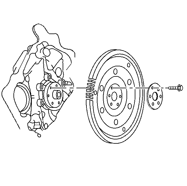
- Remove the flywheel bolts
and the flywheel.
- Mount the engine on a suitable engine stand.
Installation Procedure
- Remove engine from stand.
- Use the J 38122-A
to hold the balancer while tightening the flywheel bolts
Notice: Use the correct fastener in the correct location. Replacement fasteners
must be the correct part number for that application. Fasteners requiring
replacement or fasteners requiring the use of thread locking compound or sealant
are identified in the service procedure. Do not use paints, lubricants, or
corrosion inhibitors on fasteners or fastener joint surfaces unless specified.
These coatings affect fastener torque and joint clamping force and may damage
the fastener. Use the correct tightening sequence and specifications when
installing fasteners in order to avoid damage to parts and systems.
- Install the flywheel,
the retainer and the bolts.
Tighten
Tighten bolts to 30 N·m (22 lb ft). Then
turn all bolts an additional 45 degrees.
- Attach the engine lifting device to the engine.
- Install the engine into the vehicle and align the transaxle to
the engine.
- Install the upper transmission to engine bolts.
Tighten
Tighten bolts to 75 N·m (55 lb ft).
- Install the engine mount and the mount bracket. Refer to
Engine Mount Replacement
.
- Remove engine hoist.
- Install upper radiator hose to engine.
- Install the transaxle mount. Refer to
Transmission Front Mount Replacement
in Automatic Transaxle-4T40-E/4T45-E.
- Raise and support the vehicle. Refer to
Lifting and Jacking the Vehicle
in General Information.
- Install the lower radiator hose to engine.
- Install lower engine to transmission bolts.
Tighten
Tighten bolts to 75 N·m (55 lb ft).
- Install A/C compressor. Refer to
Air Conditioning Compressor Replacement
in HVAC.
- Install the torque converter bolts. Refer to
Transmission Replacement
in Automatic Transaxle-4T40-E/4T45-E.
- Connect the exhaust pipe.
- Install the starter. Refer to
Starter Motor Replacement
in Engine Electrical.
- Install the transaxle brace. Refer to
Transmission Replacement
in Automatic Transaxle-4T40-E/4T45-E.
- Install the crankshaft balancer. Refer to
Crankshaft Balancer Replacement
.
- Install the drive belt. Refer to
Drive Belt Replacement
.
- Install the engine splash shield. Refer to
Engine Splash Shield Replacement
in Body Front End.
- Install the front wheels. Refer to
Tire and Wheel Removal and Installation
in Tires and Wheels.
- Lower the vehicle.
- Install surge tank hose.
- Install brake booster vacuum line.
- Connect generator electrical.
- Connect the following electrical connectors:
| • | The evaporator canister (1) |
Caution: In order to avoid possible injury or vehicle damage, always replace
the accelerator control cable with a NEW cable whenever you remove the engine
from the vehicle.
In order to avoid cruise control cable damage, position the cable out
of the way while you remove or install the engine. Do not pry
or lean against the cruise control cable and do not kink the cable. You must
replace a damaged cable.
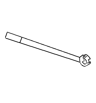
- Install the accelerator cable (1) and bracket.
- Install the cruise control assembly. Refer to
Cruise Control Module Replacement
in Cruise Control.
- Connect the oil pressure
switch.
- Install the power steering
pump.
- Connect the camshaft position
sensor.
- Connect the ignition coil and module.
- Install the fuel rail assembly. Refer to
Fuel Injection Fuel Rail Assembly Replacement
in Engine Controls-2.4L.
- Install the air intake assembly. Refer to
Air Cleaner Inlet Duct Replacement
in Engine Controls-2.4L.
- Refill the engine oil. Refer to
Engine Oil and Oil Filter Replacement
.
- Refill the engine cooling system. Refer to
Cooling System Draining and Filling
in Engine Cooling.
- Run the engine to operating temperature and retest all fluid levels.
