All of the sensors and input switches can be diagnosed using a scan tool. Following is a short description of how the sensors and switches can be diagnosed by using a scan tool. The scan tool can also be used to compare the values for a normal running engine with the engine you are diagnosing.
Engine Coolant Temperature (ECT) Sensor
The engine coolant temperature sensor is a thermistor (a resistor which changes value based on temperature) mounted in the engine coolant stream. Low coolant temperature produces a high resistance (100,000 ohms at -40°C/-40°F) while high temperature causes low resistance (70 ohms at 130°C/266°F).
The PCM supplies a 5 volt signal to the engine coolant temperature sensor through a resistor in the PCM and measures the voltage. The voltage will be high when the engine is cold, and low when the engine is hot. By measuring the voltage, the PCM calculates the engine coolant temperature. Engine coolant temperature affects most systems the PCM controls.
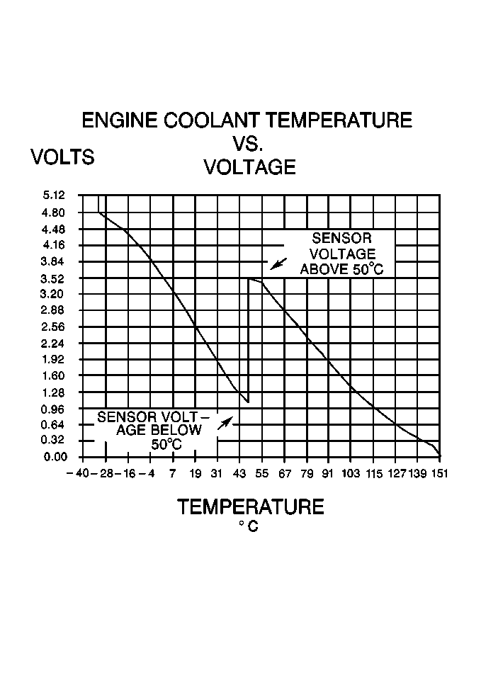
The scan tool displays engine coolant temperature in degrees. After engine start-up, the temperature should rise steadily to about 90°C (194°F) then stabilize when thermostat opens. If the engine has not been run for several hours (overnight), the engine coolant temperature and intake air temperature displays should be close to each other. A hard fault in the engine coolant sensor circuit should set DTC P0117 or DTC P0118, an intermittent fault should set a DTC P1114 or P1115. The DTC Diagnostic Aids also contains a chart to check for sensor resistance values relative to temperature. Refer to Temperature Versus Resistance .
The ECT sensor also contains another circuit which is used to operate the engine coolant temperature gauge located in the instrument panel.
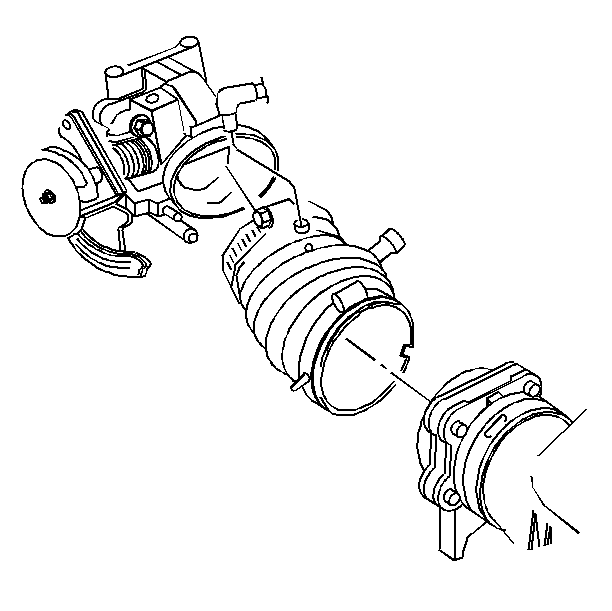
Mass Air Flow (MAF) Sensor
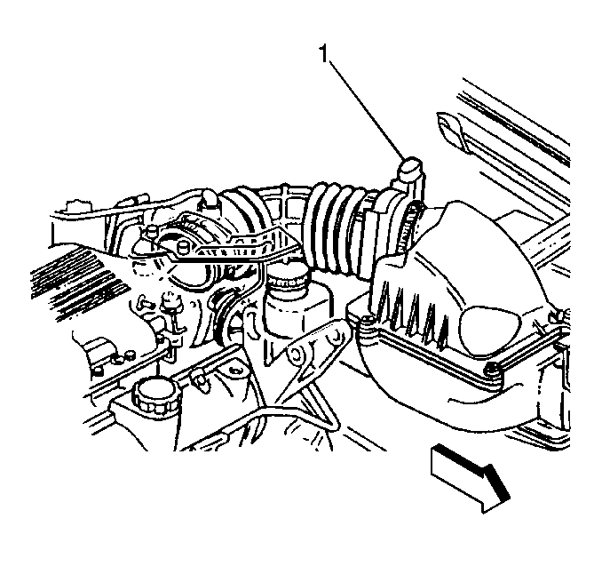
The Mass Air Flow (MAF) sensor (1) measures the amount of air which passes through it. The PCM uses this information to determine the operating condition of the engine, to control fuel delivery. A large quantity of air indicates acceleration, while a small quantity indicates deceleration or idle.
The scan tool reads the MAF value and displays it in grams per second (gm/s). At idle, it should read between 4gm/s-6gm/s on a fully warmed up engine. Values should change rather quickly on acceleration, but values should remain fairly stable at any given RPM. A failure in the MAF sensor (1) or circuit should set DTC P0101, DTC P0102, or DTC P0103.
Intake Air Temperature (IAT) Sensor
The Intake Air Temperature (IAT) sensor is a thermistor which changes value based on the temperature of air entering the engine. Low temperature produces a high resistance (100,000 ohms at -40°C/-40°F), while high temperature causes low resistance (70 ohms at 130°C/266°F). The PCM supplies a 5 volt signal to the sensor through a resistor in the PCM and measures the voltage. The voltage will be high when the incoming air is cold, and low when the air is hot. By measuring the voltage, the PCM calculates the incoming air temperature. The IAT sensor signal is used to adjust spark timing according to incoming air density.
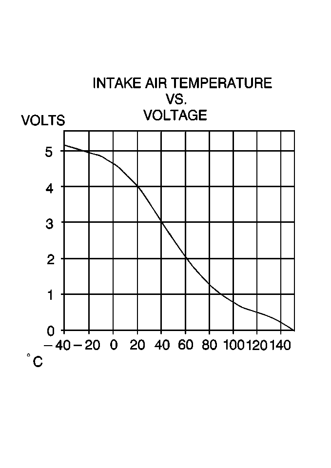
The scan tool displays temperature of the air entering the engine, which should read close to ambient air temperature when the engine is cold, and rise as the underhood temperature increases. If the engine has not been run for several hours (overnight) the IAT sensor temperature and engine coolant temperature should read close to each other. A failure in the IAT sensor circuit should set DTC P0112 or DTC P0113.
Manifold Absolute Pressure (MAP) Sensor
The Manifold Absolute Pressure (MAP) sensor (5) responds to changes in intake manifold pressure (vacuum). The MAP sensor (5) signal voltage to the PCM varies from below 2 volts at idle (high vacuum) to above 4 volts with the key on, engine not running or at wide open throttle (low vacuum).
The MAP sensor (5) is used to determine manifold pressure changes while the linear EGR flow test diagnostic is being run (refer to DTC P0401 Exhaust Gas Recirculation (EGR) Flow Insufficient ), to determine engine vacuum level for other diagnostics and to determine barometric pressure (BARO).
If the PCM detects a voltage that is lower than the possible range of the MAP sensor, DTC P0107 will be set. A signal voltage higher than the possible range of the sensor will set DTC P0108. An intermittent low or high voltage will set DTC P1107 or P1106 respectively. The PCM can also detect a shifted MAP sensor. The PCM compares the MAP sensor signal to a calculated MAP based on throttle position and various engine load factors If the PCM detects a MAP signal that varies excessively above or below the calculated value, DTC P0106 will set.
The PCM updates the MAP sensor reading at each 3X reference pulse. If the 3X reference pulse is lost the PCM will only update the MAP sensor once per ignition cycle and will retain that value until the next ignition cycle. Depending on the retained MAP sensor value, the PCM will set the appropriate high voltage DTC or low voltage DTC.
Fuel Control Heated Oxygen Sensor (HO2S 1)
The fuel control Heated Oxygen Sensor (HO2S 1) is mounted in the exhaust manifold where it can monitor the oxygen content of the exhaust gas stream. The oxygen present in the exhaust gas reacts with the sensor to produce a voltage output. This voltage should constantly fluctuate from approximately 100 mV (high oxygen content--lean mixture) to 900 mV (low oxygen content--rich mixture). The heated oxygen sensor voltage can be monitored with a scan tool. By monitoring the voltage output of the oxygen sensor, the PCM calculates what fuel mixture command to give to the injectors (lean mixture--low HO2S voltage = rich command, rich mixture--high HO2S voltage = lean command).
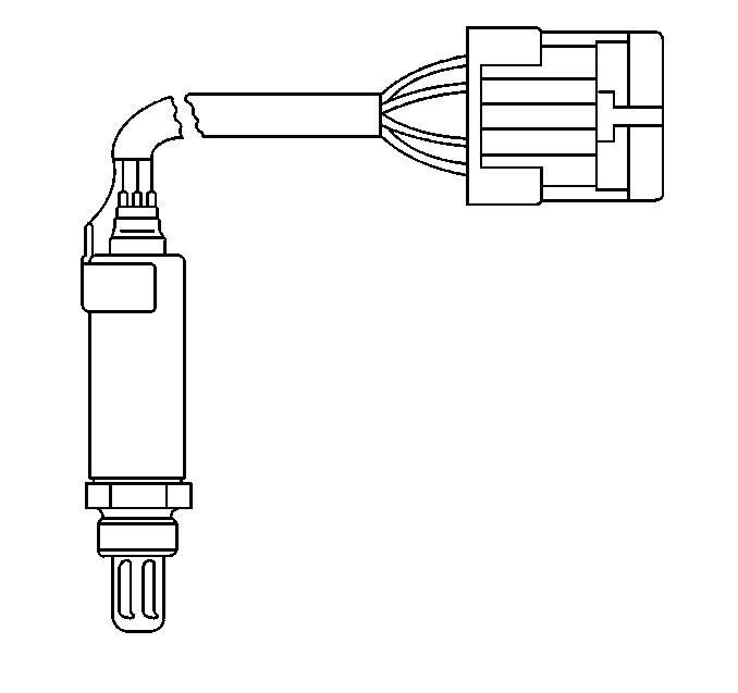
The HO2S 1 circuit, if open, should set a DTC P0134 and the scan tool will display a constant voltage between 400-500 mV. A constant voltage below 300 mV in the sensor circuit (circuit grounded) should set DTC P0131, while a constant voltage above 800 mV in the circuit should set DTC P0132. A fault in the HO2S 1 heater circuit should cause DTC P0135 to set. The PCM can also detect HO2S response problems. If the response time of an HO2S is determined to be too slow, the PCM will store a DTC that indicates degraded HO2S performance.
Catalyst Monitor Heated Oxygen Sensor (HO2S 2)
To control emissions of Hydrocarbons (HC), Carbon Monoxide (CO), and Oxides of Nitrogen (NOx), a three-way catalytic converter is used. The catalyst within the converter promotes a chemical reaction which oxidizes the HC and CO present in the exhaust gas, converting them into harmless water vapor and carbon dioxide. The catalyst also reduces NOx, converting it to nitrogen. The PCM has the ability to monitor this process using the HO2S 1 and the HO2S 2 heated oxygen sensors. The HO2S 1 sensor produces an output signal which indicates the amount of oxygen present in the exhaust gas entering the three-way catalytic converter. The HO2S 2 sensor produces an output signal which indicates the oxygen storage capacity of the catalyst; this in turn indicates the catalyst's ability to convert exhaust gases efficiently. If the catalyst is operating efficiently, the HO2S 1 signal will be far more active than that produced by the HO2S 2 sensor.
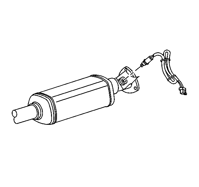
The catalyst monitor sensors operate the same as the fuel control sensors. Although the HO2S 2 sensors main function is catalyst monitoring, it also plays a limited role in fuel control. If the sensor output indicates a voltage either above or below the 450 millivolt bias voltage for an extended period of time, the PCM will make a slight adjustment to fuel trim to ensure that fuel delivery is correct for catalyst monitoring.
A problem with the HO2S 2 signal circuit should set DTC P0137, P0138 or P0140, depending on the specific condition. A fault in the heated oxygen sensor heater element or its ignition feed or ground will result in slower oxygen sensor response. This may cause erroneous Catalyst monitor diagnostic results. A fault in the HO2S 2 heater circuit should cause DTC P0141 to set.
Throttle Position (TP) Sensor
The Throttle Position (TP) sensor (2) is a potentiometer connected to the throttle shaft on the throttle body. By monitoring the voltage on the signal line, the PCM (1) calculates throttle position. As the throttle valve (3) angle is changed (accelerator pedal moved), the TP sensor (2) signal also changes. At a closed throttle position, the output of the TP sensor (2) is low. As the throttle valve opens, the output increases so that at Wide Open Throttle (WOT), the output voltage should be above 4 volts.
The PCM (1) calculates fuel delivery based on throttle valve (3) angle (driver demand). A broken or loose TP sensor (2) may cause intermittent bursts of fuel from an injector and unstable idle because the PCM (1) thinks the throttle is moving. A hard failure in the TP sensor 5 volts reference or signal circuits should set either a DTC P0122 P0123, P1350. A hard failure with the TP sensor ground circuit may set DTCs P0107, P0112, P0123 or P0117. Once a DTC is set, the PCM will use an artificial default value based on engine RPM and mass air flow for throttle position and some vehicle performance will return. A high idle may result when either DTC P0122 or DTC P0123 is set.
The PCM (1) can detect intermittent TP sensor (2) faults. DTC P1121 or DTC P1122 will set if an intermittent high or low circuit failure is being detected. The PCM (1) can also detect a shifted TP sensor (2). The PCM (1) monitors throttle position and compares the actual TP sensor reading to a predicted TP value calculated from engine speed. If the PCM (1) detects an out of range condition, DTC P0121 will be set.
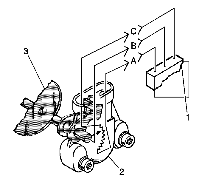
EGR Pintle Position Sensor
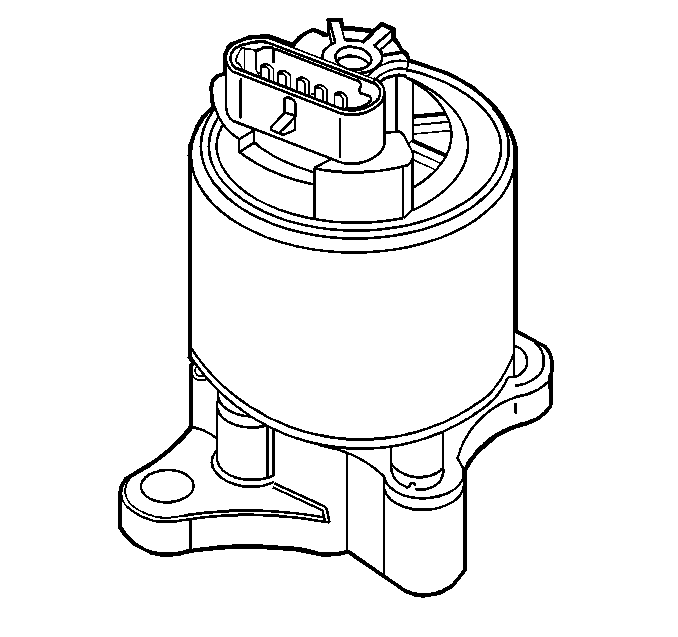
The EGR pintle position sensor is an integral part of the EGR valve assembly. This sensor can not be serviced separately from the EGR valve assembly.
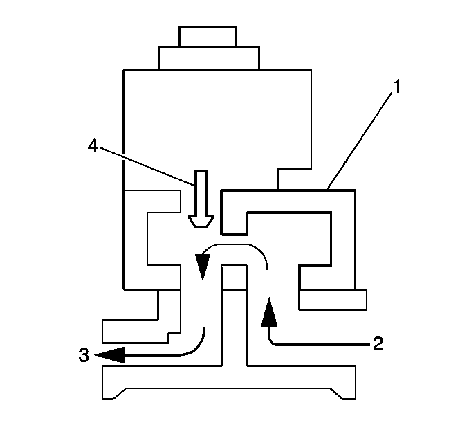
The PCM monitors the EGR valve pintle position (4) input to ensure that the valve (1) responds properly to commands from the PCM and to detect a fault if the pintle position sensor and control circuits are open or shorted. If the PCM detects a pintle position signal voltage outside the normal range of the pintle position sensor, or a signal voltage that is not within a tolerance considered acceptable for proper EGR system operation, the PCM will set DTC P1406.
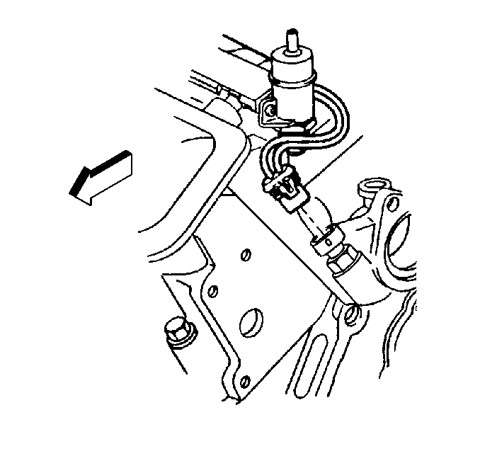
Knock Sensor (KS)
The knock sensors detect abnormal vibration (spark knocking) in the engine. The sensors are mounted in the engine block near the cylinders. The knock sensors produce an AC voltage signal under all engine operating conditions. The PCM adjusts the Ignition Control (IC) spark timing based on the amplitude and frequency of the KS signal being received.
The PCM contains integrated Knock Sensor (KS) diagnostic circuitry. The PCM uses the circuitry to diagnose the KS sensors and related wiring. The PCM calculates an average voltage of each knock sensor's signals and takes instantaneous signal voltage readings. The PCM uses the instantaneous signal voltage readings to determine the state of the knock sensor circuitry. If the knock sensor system is operating normally, the PCM should monitor instantaneous KS signal voltage readings varying outside a voltage range above and below the calculated average voltage. If the PCM malfunctions in a manner which will not allow proper diagnosis of the KS circuit DTC 325 will set. DTCs P0327 and P0332 are designed to diagnose the knock sensors, and related wiring, so problems encountered with the KS system should set a DTC. Refer to Knock Sensor (KS) System Description for a complete description of the knock sensor system.
A/C Request Signal
This signal indicates to the PCM that an A/C mode is selected at the A/C control head. The PCM uses this information to adjust the idle speed before turning on the A/C clutch. If this signal is not available to the PCM, the A/C compressor will be inoperative.
Refer to HVAC Connector End Views in HVAC System - Manual for the A/C clutch wiring diagrams and the diagnosis of A/C clutch electrical system.
A/C Refrigerant Pressure Sensor
The A/C refrigerant pressure sensor signal indicates high side refrigerant pressure to the PCM. The PCM uses this information to adjust the idle air control valve to compensate for the higher engine loads present with high A/C refrigerant pressures and to control the cooling fans. A fault in the A/C refrigerant pressure sensor signal will cause DTC P0530 to set. Refer to DTC P0530 Air Conditioning (A/C) Refrigerant Pressure Sensor Circuit .
TCC Brake Switch
The TCC brake switch signal to the PCM indicates when the brake pedal is applied. The TCC brake switch information is used by the PCM mainly to control the Transaxle torque converter clutch.
Refer to DTC P0724 Brake Switch Circuit High Input for a complete description and TCC brake switch diagnosis.
Transaxle Range Switch
The Transaxle Range Switch is part of the Transaxle Park/Neutral Position (PNP) switch mounted on the transaxle manual shaft. The 4 inputs from the transaxle range switch indicate to the PCM which position is selected by the Transaxle selector lever. This information is used for transmission shift control, ignition timing, EVAP canister purge, EGR and IAC valve operation.
The combination of the four transaxle range input states determine the PCM commanded shift pattern. The input voltage level at the PCM is high (B+) when the transaxle range switch is open and low when the switch is closed to ground. The state of each input is represented on the scan tool as X=high voltage level, 0=low voltage level. The four parameters represent transaxle range switch Parity, A, B, and C inputs respectively.
Gear Selector Position | Scan Tool Trans Range PABC Display X=High 0=Low | |||
|---|---|---|---|---|
P | A | B | C | |
Park (P) | 0 | 0 | X | X |
Reverse (R) | X | 0 | 0 | X |
Neutral (N) | 0 | X | 0 | X |
Drive4 (OD) | X | X | 0 | 0 |
Drive3 (3) | 0 | 0 | 0 | 0 |
Drive2 (2) | X | 0 | X | 0 |
Drive 1 (1) | 0 | X | X | 0 |
Transaxle Fluid Temperature (TFT) Sensor

The Transaxle fluid temperature sensor is a thermistor which changes value based on the temperature of the Transaxle fluid. A high Transaxle fluid temperature may cause the vehicle to operate in Hot Mode. While in Hot Mode, shift points may be altered, 4th gear disabled, and TCC forced on in 2nd gear. A failure in the TFT sensor or associated wiring should cause DTC P0712 or P0713 to set. In this case, engine coolant temperature will be substituted for the TFT sensor value, and the Transaxle will operate normally. Refer to DTC P0711 TFT Sensor Circuit Range/Performance for a complete description of the TFT sensor.
Vehicle Speed Sensor (VSS)
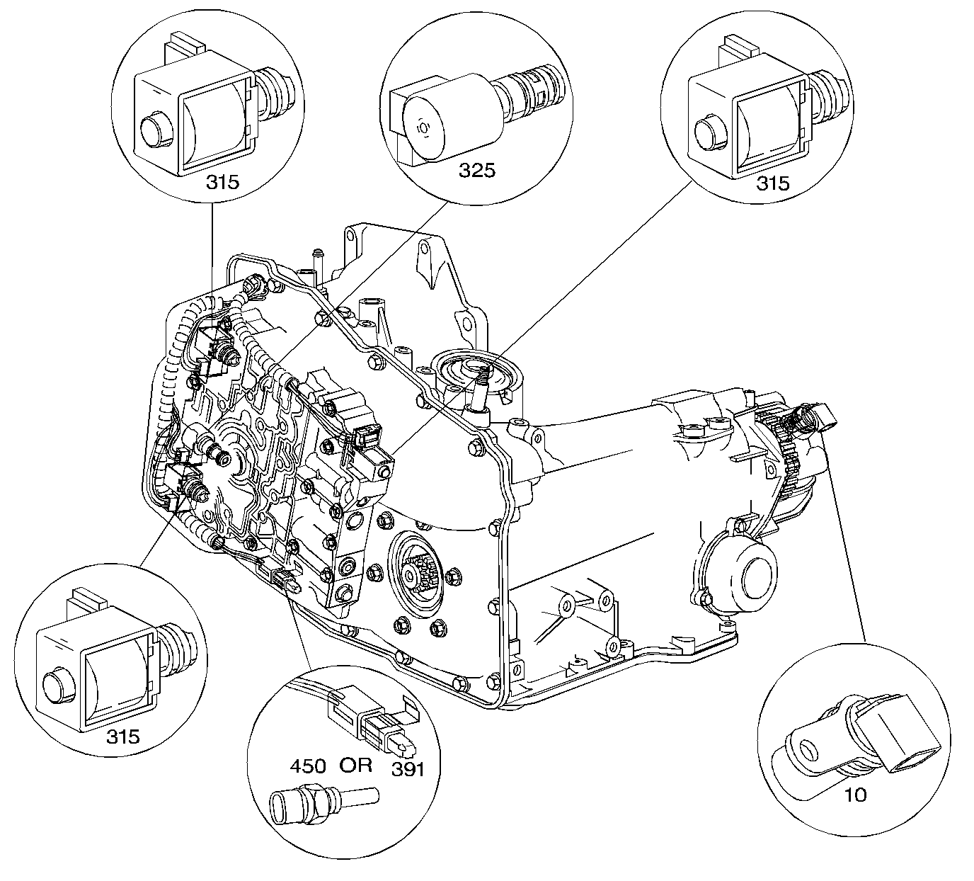
Electronic Component Locations