Refer to
Vehicle Speed Sensor
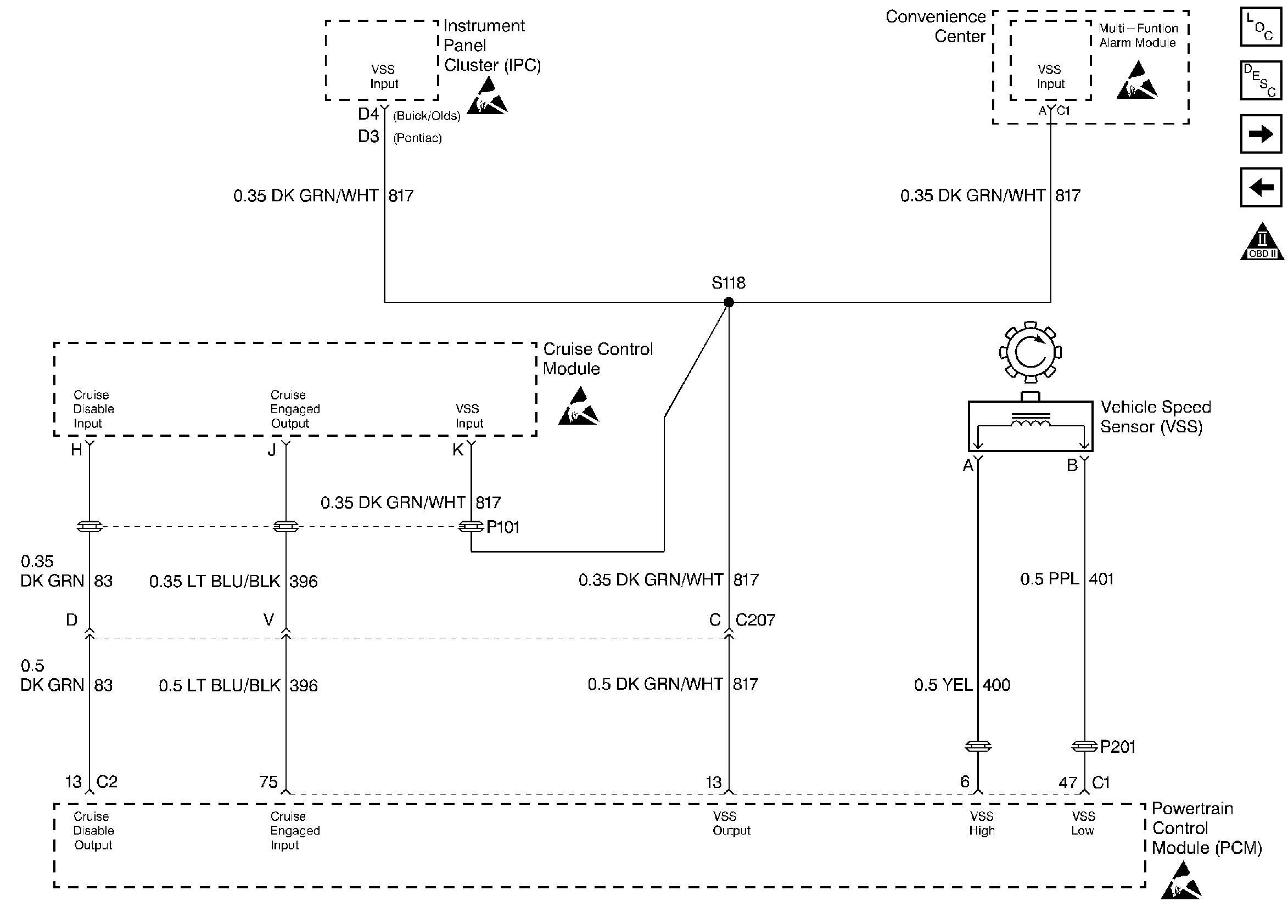
.
Circuit Description
The stepper motor cruise control module sends the cruise status input to the PCM to indicate when cruise control is engaged. The PCM monitors the cruise status signal while commanding cruise to be disengaged by grounding the cruise inhibit circuit. Any of the following conditions may cause the PCM to inhibit cruise control operation:
| • | Engine not running long enough for cruise control operation. |
| • | Transaxle range inputs indicate park, neutral, low, or reverse gear selected. |
| • | Engine speed is too high or too low. |
| • | Vehicle speed is too high or too low. |
| • | ABS system is active for longer than 2 seconds. |
| • | Vehicle acceleration or deceleration rate is too high. |
Conditions for Setting the DTC
| • | The PCM is commanding the SMCC module to not allow cruise control operation (Cruise Inhibit circuit grounded). |
| • | The Cruise Status input to the PCM indicates that cruise control is still active. |
| • | Above conditions for longer than 1 second. |
Action Taken When the DTC Sets
| • | The PCM will not illuminate the malfunction indicator lamp (MIL). |
| • | The PCM will store conditions which were present when the DTC set as Failure Records data only. This information will not be stored as Freeze Frame data. |
Conditions for Clearing the MIL/DTC
| • | A History DTC will clear after 40 consecutive warm-up cycles have occurred without a malfunction. |
| • | The DTC can be cleared by using the scan tool Clear Info function. |
Diagnostic Aids
Check for the following conditions:
| • | Poor connection at PCM. Inspect harness connectors for backed out terminals, improper mating, broken locks, improperly formed or damaged terminals, and poor terminal to wire connection. |
| • | Damaged harness. Inspect the wiring harness for damage. If the harness appears to be OK, observe the Cruise Status display on the scan tool while moving connectors and wiring harnesses related to the Stepper Motor Cruise Control module. A change in the display will indicate the location of the fault. |
If DTC P1554 cannot be duplicated, the information included in the Failure records data can be useful in determining how many ignition cycles have passed since the DTC was last set.
Step | Action | Value(s) | Yes | No |
|---|---|---|---|---|
1 | Was the Powertrain On-Board Diagnostic System Check performed? | -- | Go to Powertrain OBD System Check | |
2 | Ignition ON, observe Cruise Engaged display on the scan tool. Does Cruise Engaged display YES? | -- | ||
3 |
Is voltage greater than the specified value? | 7V | ||
4 |
Was a problem found? | -- | ||
5 |
Is the test light ON? | -- | ||
6 |
Is the test light ON? | -- | ||
7 |
Is the voltage near the specified value? | B+ | ||
8 |
Did an active DTC P1554 set? | -- | Refer to Diagnostic Aids | |
9 |
Was a problem found? | -- | ||
10 |
Was a problem found? | -- | ||
11 | Replace the stepper motor cruise control module. Is action complete? | -- | -- | |
12 | Replace the PCM. Important: The replacement PCM must be programmed. Refer to PCM Replacement/Programming. Is action complete? | -- | -- | |
13 | Locate and repair short to ground in the cruise inhibit circuit. Is action complete? | -- | -- | |
14 |
Did DTC P1554 set? | -- | Repair complete |
