Front Brake Caliper Replacement Single Piston
Removal Procedure
- Remove two-thirds of the brake fluid from the master cylinder reservoir.
- Raise the vehicle and support the vehicle with proper safety stands. Refer to Lifting and Jacking the Vehicle in General Information.
- Remove the tire and wheel assembly. Refer to Tire and Wheel Removal and Installation in Tires and Wheels.
- Position a C-clamp over the outer brake shoe and the caliper.
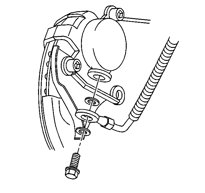
- Disconnect the brake hose from the caliper.
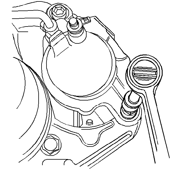
- Remove the caliper mounting bolts.
- Remove the caliper.
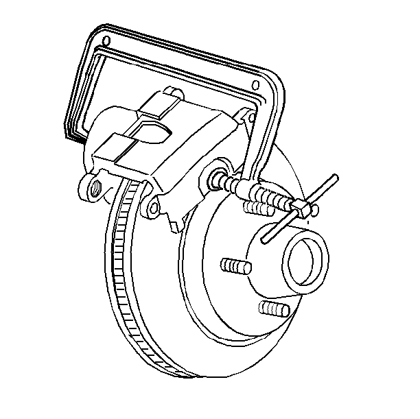
| 4.1. | Tighten the C-clamp until the piston bottoms in the caliper bore. |
| 4.2. | Remove the C-clamp. |
Inspection Procedure
- Inspect the mounting bolts and sleeves for corrosion. Do not polish away any corrosion.
- Replace corroded mounting bolts and sleeves.
Installation Procedure
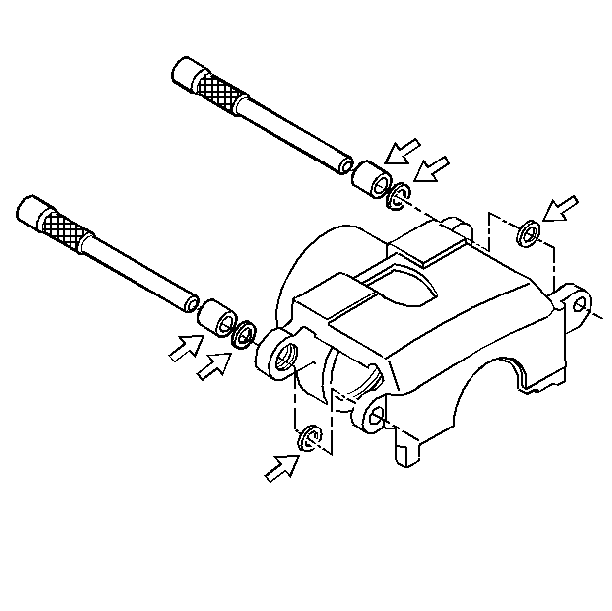
- Lubricate the sleeves and bushings with silicone brake lube.
- Install the bushings and sleeves in the caliper.
- Install the caliper and the two mounting bolts.
- Connect the brake hose to the caliper, if removed.
- Measure the clearance between the caliper and the steering knuckle.
- Install the tire and wheel assembly. Refer to Tire and Wheel Removal and Installation in Tires and Wheels.
- Remove the safety stands and lower the vehicle.

Important: Lift the inner edge caliper boot next to the piston. Press out any trapped air. The boot must lay flat below the level of the piston face.
Notice: Use the correct fastener in the correct location. Replacement fasteners must be the correct part number for that application. Fasteners requiring replacement or fasteners requiring the use of thread locking compound or sealant are identified in the service procedure. Do not use paints, lubricants, or corrosion inhibitors on fasteners or fastener joint surfaces unless specified. These coatings affect fastener torque and joint clamping force and may damage the fastener. Use the correct tightening sequence and specifications when installing fasteners in order to avoid damage to parts and systems.

Tighten
Tighten the mounting bolts to 51 N·m (38 lb ft).
Notice: Make sure the brake hose is not twisted or kinked after installation. Damage to the hose could result.

Tighten
Tighten the brake hose bolt to 54 N·m (40 lb ft).
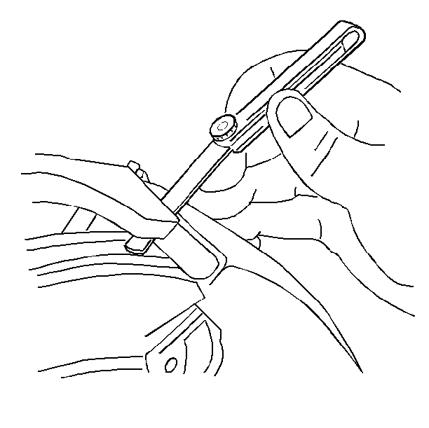
| 5.1. | Measure each end of the caliper individually. |
| 5.2. | Add the two measurements together. The total measurement should be 0.26-0.60 mm (0.010-0.024 in). |
| Important: If necessary, remove the front brake caliper and file the ends of the steering knuckle to obtain the proper clearance. If the total clearance exceeds the specified range, check the steering knuckle and front brake caliper for damage and replace as necessary. |
Front Brake Caliper Replacement Dual Piston
Removal Procedure
- Remove two-thirds of the brake fluid from the master cylinder reservoir.
- Raise the vehicle and support the vehicle with proper safety stands. Refer to Lifting and Jacking the Vehicle in General Information.
- Remove the tire and wheel assembly. Refer to Tire and Wheel Removal and Installation in Tires and Wheels.
- Position a C-clamp over the outer brake pad and the caliper.
- Disconnect the brake hose from the caliper when removing the caliper for overhaul or replacement.
- Remove the caliper guide pin bolts.
- Remove the caliper from the caliper bracket.
- If you did not disconnect the brake hose, suspend the caliper.

| 4.1. | Tighten the C-clamp until the piston bottoms in the caliper bore. |
| 4.2. | Remove the C-clamp. |
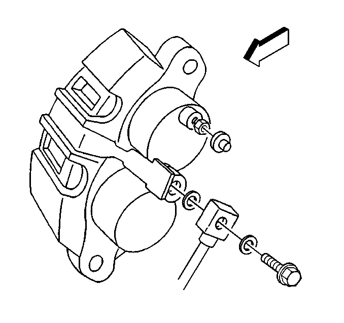
| 5.1. | Disconnect the brake hose fitting and two gaskets. |
| 5.2. | Discard the gaskets. |
| 5.3. | Plug the hole in the caliper housing and in the brake hose fitting. |
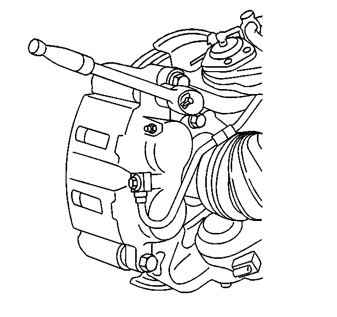
Notice: Do not allow the brake components to hang from the flexible brake hoses. Damage to the brake hoses could result.
Inspection Procedure
- Inspect the caliper guide pin bolts for corrosion. Do not polish away any corrosion.
- Inspect the linings for wear.
- Inspect the brake hose fitting bolt. If the through-hole is blocked, remove the blockage or replace the bolt.
Replace corroded bolts.
Replace the linings if the linings are tapered beyond 0.15 mm (0.006 in).
Installation Procedure
- Install the linings.
- Install the caliper over the rotor and into the anchor bracket.
- Install the two caliper guide pin bolts to the caliper bracket.
- Install the brake hose fitting, two new gaskets, and the brake hose fitting bolt, if removed.
- Bleed the caliper, if separated from the brake hose in removal. Refer to Hydraulic Brake System Bleeding in Hydraulic Brakes.
- Install the tire and wheel assembly. Refer to Tire and Wheel Removal and Installation in Tires and Wheels.
- Remove the safety stands and lower the vehicle.
- With the engine running, firmly pump the brake pedal three times.
- Inspect the brake system for leaks.
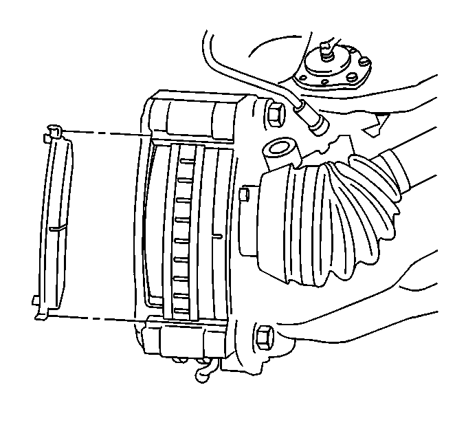
Important: Lift the inner edge of the caliper boots next to the pistons. Press out any trapped air. The boots must lay flat below the level of the piston faces.
Notice: Use the correct fastener in the correct location. Replacement fasteners must be the correct part number for that application. Fasteners requiring replacement or fasteners requiring the use of thread locking compound or sealant are identified in the service procedure. Do not use paints, lubricants, or corrosion inhibitors on fasteners or fastener joint surfaces unless specified. These coatings affect fastener torque and joint clamping force and may damage the fastener. Use the correct tightening sequence and specifications when installing fasteners in order to avoid damage to parts and systems.

Tighten
Tighten the bolts to 115 N·m (85 lb ft).
Notice: Make sure the brake hose is not twisted or kinked after installation. Damage to the hose could result.

Tighten
Tighten the brake hose bolt to 54 N·m (40 lb ft).
