For 1990-2009 cars only
Removal Procedure
- Position the front wheels and the steering wheel straight ahead.
- Tilt the cab. Refer to Cab Tilting .
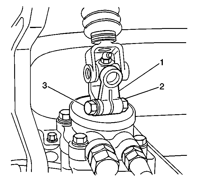
- Mark the position of the steering gear input shaft and the lower cardan joint (1) of the lower steering shaft.
- Remove the following components from the lower cardan joint (1):
- Gently pry the lower cardan joint (1) off from the steering gear input shaft.
- Retract the lower steering shaft toward the cab.
- Close the cab slowly. Ensure that the lower steering shaft does not contact the cab.
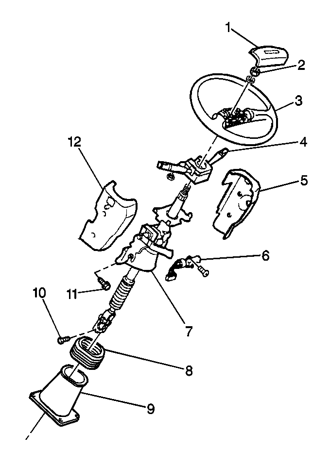
- Remove the steering wheel (3). Refer to Steering Wheel Replacement .
- Remove the following components from the upper steering shaft assembly (7):
- Remove the electrical connector from the ignition switch (6).
- Remove the following components from the upper steering shaft assembly (7):
- Disconnect the electrical connector from the ignition switch (6).
- Remove the following components from the upper steering shaft assembly (7):
- Remove the following components from the wire harness:
- Remove the tie wraps from the wiring harness, as necessary.
- Remove the following components from the vehicle:

| 4.1. | The nut (2) |
| 4.2. | The washer |
| 4.3. | The cardan bolt (3) |

| • | The left side cowl half screws |
| • | The right side cowl half screws |
| • | The left side cowl half (12) |
| • | The right side cowl half (5) |
| 11.1. | The combination switch screws |
| 11.2. | The combination switch (4) |
| 13.1. | The ignition switch screws |
| 13.2. | The ignition switch (6) |
| • | The wiring harness screw |
| • | The clamp |

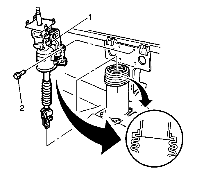
| • | Upper steering shaft assembly mounting bolts (2) |
| • | Upper steering shaft assembly (1) |
Installation Procedure
- Install the following components to the vehicle:
- Connect the ignition switch (6) to the upper steering shaft assembly (7). Secure the ignition switch with the following components:
- Connect the electrical connector to the ignition switch (6).
- Connect the combination switch (4) to the upper steering shaft assembly (7). Secure the combination switch with screws.
- Connect the electrical connector to the combination switch (4).
- Install the wiring harness clamp to the upper steering shaft assembly (7). Secure the clamp with a screw.
- Install the tie wraps to the wiring harness, as necessary.
- Install the following components to the upper steering shaft assembly:
- Position the boot (8) over the lower steering shaft cover (9).
- Install the steering wheel (3).
- Slowly tilt the cab. Ensure that the lower steering shaft does not come in contact with the cab.
- Align the marks on the steering gear input shaft and the lower cardan joint (1) of the lower steering shaft.
- Position the lower steering shaft lower cardan joint (1) on the steering gear input shaft.
- Install the following components:
- Lower the cab.

| • | Upper steering shaft assembly (1) |
| • | Upper steering shaft assembly mounting bolts (2) |

| • | The wiring harness clamp |
| • | The screws |
| • | Left side cowl half (12) |
| • | Right side cowl half (5) |
| • | Secure the cowl halves with screws |
Notice: Refer to Fastener Notice in the Preface section.

| • | The lower cardan joint bolt (3) |
| • | The lower cardan joint washer |
| • | The lower cardan joint nut (2) |
Tighten
Tighten to 55 N·m (41 lb ft).
