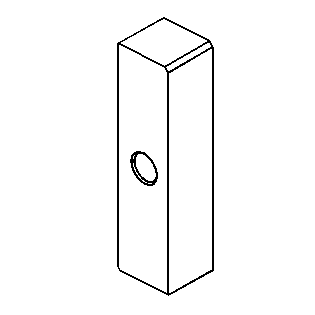
Pinion Depth Adjustment 8.0 Inch Axle
Tools Required
| • | J 34925 Pinion Setting Gage and Components |
| • | J 45230 Pinion Setting Gage Block |
Important: Make sure all of the tools, the differential side bearing bores, and the pinion bearing cups are clean before proceeding.
- Lubricate the pinion bearings with axle lubricant. Refer to
Fluid and Lubricant Recommendations
.
- Install the pinion bearings into the axle housing.
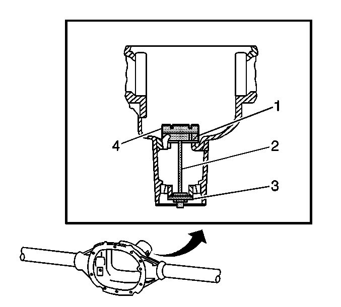
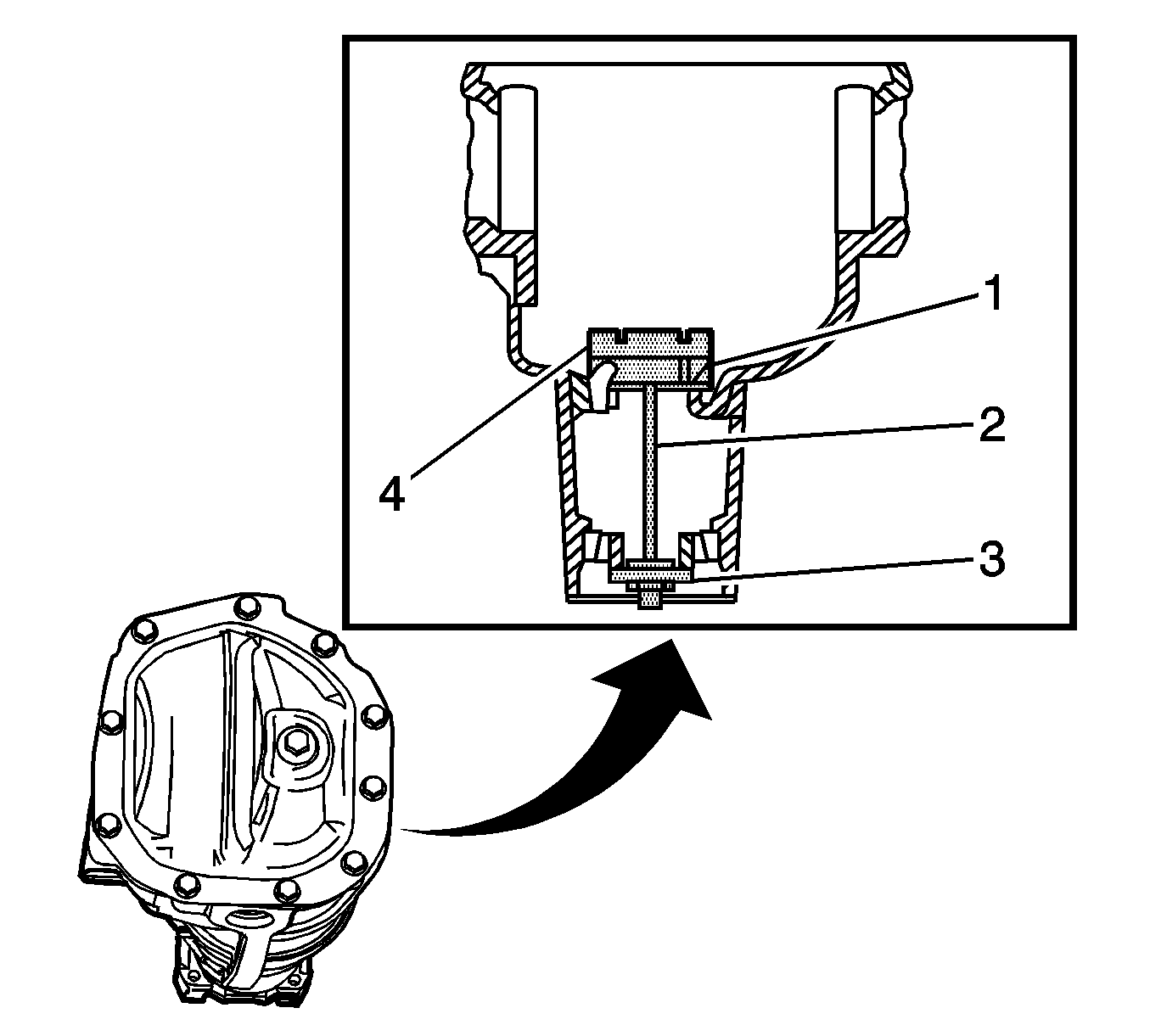
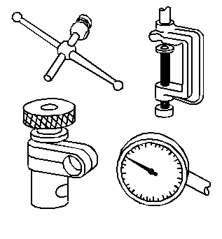
- Assemble the J 21777-35 (1), the
J 21777-43
(2), the
J 21777-42
(3), and the
J 45230
(4) into the axle housing as shown.
Notice: Refer to Fastener Notice in the Preface section.
- While holding the
J 21777-43
stationary, install an inch-pound torque wrench on the nut of the
J 21777-43
.
Tighten
Tighten the nut on the
J 21777-43
until a rotating torque of 1.7-2.8 N·m (15-25 lb in) is obtained.
- Rotate the assembly several times in both directions in order to seat the pinion bearings.
- Check the rotating torque of the assembly. If the torque is less than 1.7 N·m (15 lb in), continue to tighten the nut on the
J 21777-43
until a rotating torque of 1.7-2.8 N·m
(15-25 lb in) is obtained.
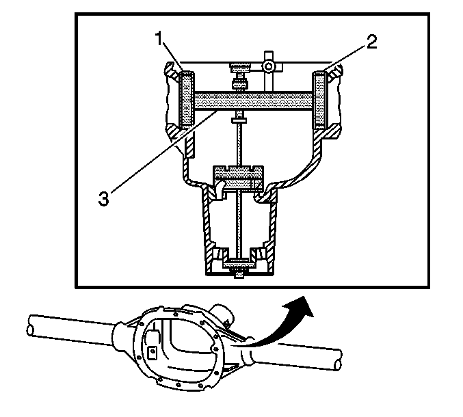
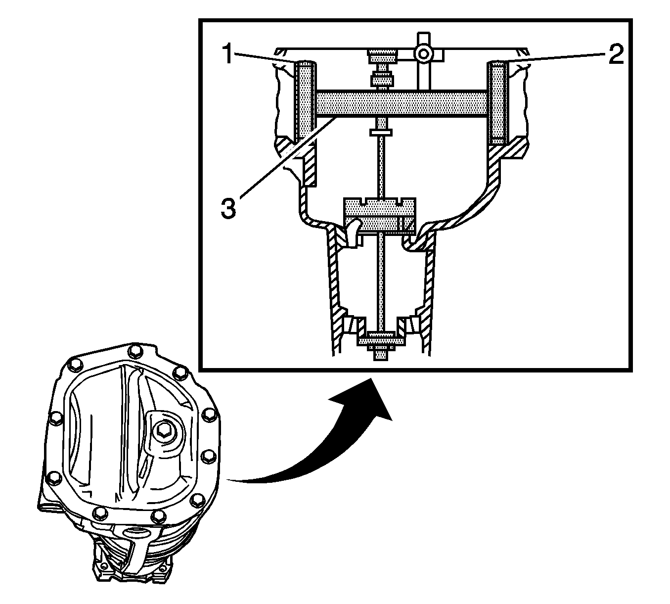
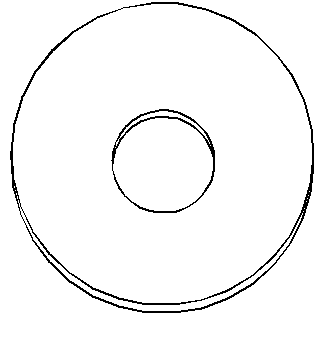
- Assemble the
J 21777-45
(1,
2) to the J 21777-1 (3), as shown.
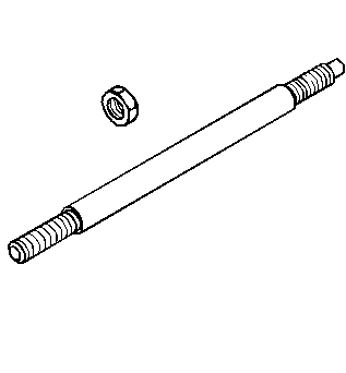
- Rotate the J 21777-1 within the
J 21777-45
. The J 21777-1 must rotate back and forth freely within the discs. If the J 21777-1 does not rotate freely, disassemble the components,
inspect for proper seating and/or mis-aligned components and re-assemble.
- Align the plunger of the J 21777-1 (1) to the
J 45230
(2).
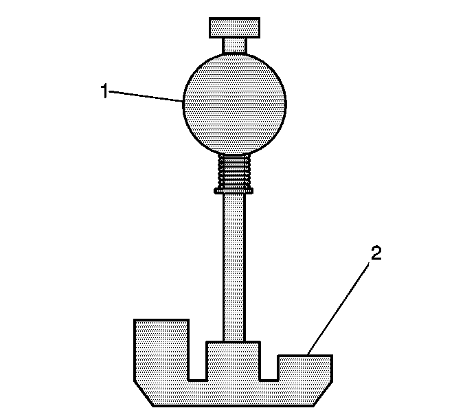
- Install the
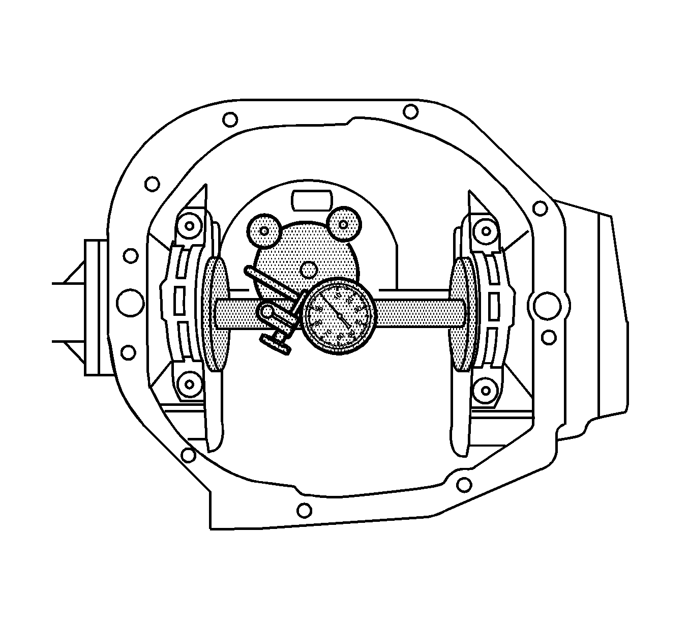
J 8001
to the J 21777-1 as follows:
| 10.1. | Loosely clamp the
J 8001
onto the stem on the J 21777-1. |
| 10.2. | Place the contact pad of the
J 8001
onto the mounting post of the J 21777-1. |
| 10.3. | With the contact pad of the
J 8001
touching the mounting post of the J 21777-1, loosen the lock nut on the
J 8001
and push down on the
J 8001
until the needle of the
J 8001
has turned 3/4 of a turn clockwise. |
| 10.4. | Tighten the clamp on the
J 8001
finger tight. |
- Move the plunger of the J 21777-1 back and forth until the needle of the
J 8001
indicates the greatest deflection.
The deflection is the point where the needle changes direction.
- At the greatest point of deflection, move the housing of the
J 8001
until the needle indicates ZERO.
- Move the plunger of the J 21777-1 back and forth again to verify the zero setting. Adjust the housing of the
J 8001
as necessary to set the needle to zero.
- Rotate the plunger of the J 21777-1 away from the
J 45230
until it no longer touches the
J 45230
or the J 21777-29.
- The value indicated on the
J 8001
is the thickness of the shim needed in order to set the depth of the pinion.
- Select the shim that indicates the proper thickness. Measure the shim with a micrometer in order to verify that the thickness is correct.
- Remove the pinion depth setting tools.
- Remove the pinion bearings.
- Install the pinion shim between the pinion gear and the inner pinion bearing. Refer to
Drive Pinion Bearings Replacement
.
Pinion Depth Adjustment 8.6 Inch Axle
Tools Required
| • | J 34925 Pinion Setting Gage and Components |
Important: Make sure all of the tools, the differential side bearing bores, and the pinion bearing cups are clean before proceeding.
- Lubricate the pinion bearings with axle lubricant. Refer to
Fluid and Lubricant Recommendations
.
- Install the pinion bearings into the axle housing.
- Assemble the J 21777-40 (1), the
J 21777-43
(2), the
J 21777-42
(3), and the J 23597-11 (4) into the axle housing as shown.
Notice: Refer to Fastener Notice in the Preface section.
- While holding the
J 21777-43
stationary, install an inch-pound torque wrench on the nut of the
J 21777-43
.
Tighten
Tighten the nut on the
J 21777-43
until a rotating torque of 1.7-2.8 N·m (15-25 lb in) is obtained.
- Rotate the assembly several times in both directions in order to seat the pinion bearings.
- Check the rotating torque of the assembly. If the torque is less than 1.7 N·m (15 lb in), continue to tighten the nut on the
J 21777-43
until a rotating torque
of 1.7-2.8 N·m (15-25 lb in) is obtained.
- Assemble the
J 21777-45
(1, 2) to the J 23957-1 (3)
as shown.
- Rotate the J 23957-1 within the
J 21777-45
. The J 23957-1 must rotate back and forth freely within the discs. If the J 23957-1 does not rotate freely, disassemble the components,
inspect for proper seating and/or mis-aligned components and re-assemble.
- Align the plunger of the J 23957-1 (1) to the J 23597-11 (2).
- Install the
J 8001
to the J 23957-1 as follows:
| 10.1. | Loosely clamp the
J 8001
onto the stem on the J 23957-1. |
| 10.2. | Place the contact pad of the
J 8001
onto the mounting post of the J 23957-1. |
| 10.3. | With the contact pad of the
J 8001
touching the mounting post of the J 23957-1, loosen the lock nut on the
J 8001
and push down on the
J 8001
until the needle the
J 8001
has turned 3/4 of a turn clockwise. |
| 10.4. | Tighten the clamp on the
J 8001
finger tight. |
- Move the plunger of the J 23957-1 back and forth until the needle of the
J 8001
indicates the greatest deflection.
The deflection is the point where the needle changes direction.
- At the greatest point of deflection, move the housing of the
J 8001
until the
needle indicates ZERO.
- Move the plunger of the J 23957-1 back and forth again to verify the zero setting. Adjust the housing of the
J 8001
as necessary to set the needle to zero.
- Rotate the plunger of the J 23957-1 away from the J 23597-11 until it no longer touches the J 23597-11 or the J 21777-29.
- The value indicated on the
J 8001
is the thickness of the shim needed in order to set the depth of the pinion.
- Select the shim that indicates the proper thickness. Measure the shim with a micrometer in order to verify that the thickness is correct.
- Remove the pinion depth setting tools.
- Remove the pinion bearings.
- Install the pinion shim between the pinion gear and the inner pinion bearing. Refer to
Drive Pinion Bearings Replacement
.
