Removal Procedure
- Disable the SIR system. Refer to SIR Disabling and Enabling.
- Remove the steering wheel. Refer to Steering Wheel Replacement.
- Remove the tilt lever. Refer to Tilt Lever Replacement.
- Remove the knee bolster. Refer to Knee Bolster Replacement.
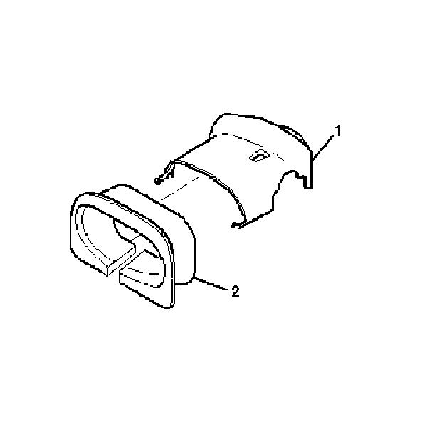
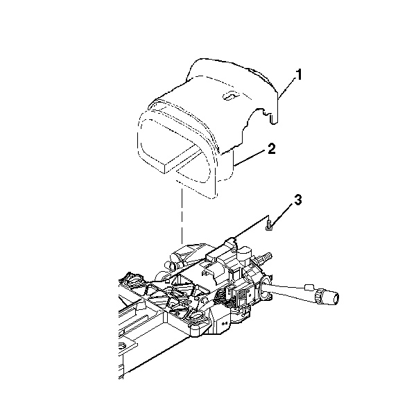
- Disengage the closeout trim cover (2) from the upper trim cover (1) in the following order:
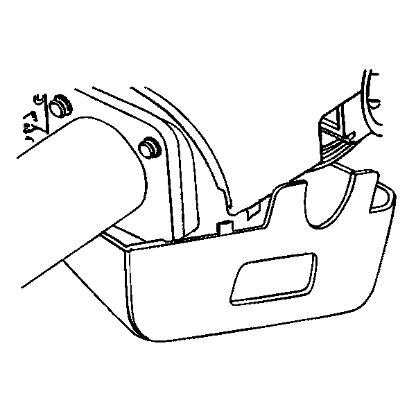
- If necessary, remove the 2 pan head tapping screws (2) from the lower trim cover (1).
- Gently unsnap the lower trim cover from the upper trim cover.
- If equipped, disconnect the electrical connector for the power pedal switch.
- Remove the lower trim cover.
- Unclip the power pedal switch from the lower cover.
- If necessary, remove 1 TORX® head screw (3) from the upper trim cover (1) and the closeout trim cover (2) for removal.
- If no screw is present, remove the upper trim cover (1) with the closeout trim cover (2).
Warning: Refer to SIR Warning in the Preface section.
Caution: Remove the closeout trim cover following the exact procedure listed below in order not to damage the snaps on the upper trim cover.
| 5.1. | Stand in front of the column from the drivers point of view. |
| 5.2. | On the left side, gently pull downwards on the left side of the closeout trim cover to loosen 1 snap. Do NOT fully remove the closeout trim cover. |
| 5.3. | On the right side, gently pull downwards on the right side of the closeout trim cover to loosen 1 snap. Do NOT fully remove the closeout trim cover. |
| 5.4. | Starting from the left side of the trim covers, gently roll the closeout trim cover to the right to disengage the remaining 4 snaps. |
Note: You must inspect for 2 pan head tapping screws (2) in the lower trim cover (1) before removal.
Note: You must inspect for 1 TORX® head screw (3) in the upper trim cover (1) before removal.
Installation Procedure
- Install the upper trim cover (1) with the closeout trim cover (2) and secure by using 1 TORX® head screw (3).
- If equipped, install the power pedal switch onto the lower trim cover.
- Plug in the electrical connector for the power pedal switch.
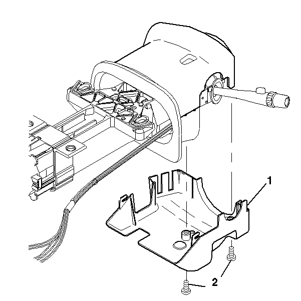
- Install the lower trim cover (1).
- Connect the lower trim cover (1) to the closeout trim cover.
- Install 2 pan head tapping screws (2).
- Install the upper and lower trim covers onto the steering column.
- Gently snap the upper and lower trim covers together.
- Install the closeout trim cover (2) onto the upper trim cover (1).
- Install the knee bolster. Refer to Knee Bolster Replacement.
- Install the tilt lever. Refer to Tilt Lever Replacement.
- Install the steering wheel. Refer to Steering Wheel Replacement.
- Enable the SIR system. Refer to SIR Disabling and Enabling.
Caution: Refer to Fastener Caution in the Preface section.
Note: If the snap on/off feature on the trim covers was damaged during the removal procedure, you must use screws for the installation procedure. If screws were present in the trim covers before the removal procedure, you must use the screws during the installation procedure.
If there was not any damage done to the trim covers during the removal procedure and no screws were present, proceed to step 7.Tighten
Tighten the screw to 1 N·m (9 lb in).
Tighten
Tighten the screws to 3.5 N·m (31 lb in).
