Removal Procedure
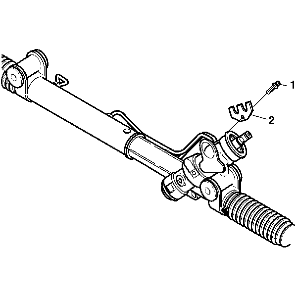
- Remove the TORX® screw (1) from the cylinder line retaining plate (2) at the valve end.
- Remove the cylinder line retaining plate (2).
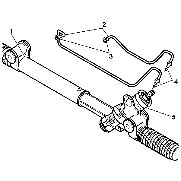
- Loosen both cylinder line nuts (3) on cylinder end of the gear assembly (1).
- Remove both cylinder line assemblies (2) from the rack and pinion gear assembly (1).
- Remove and discard the O-rings seals (4) from the valve end (5).
Important: Protect the boots from sharp tools and from the sharp edges of surrounding components.
Installation Procedure
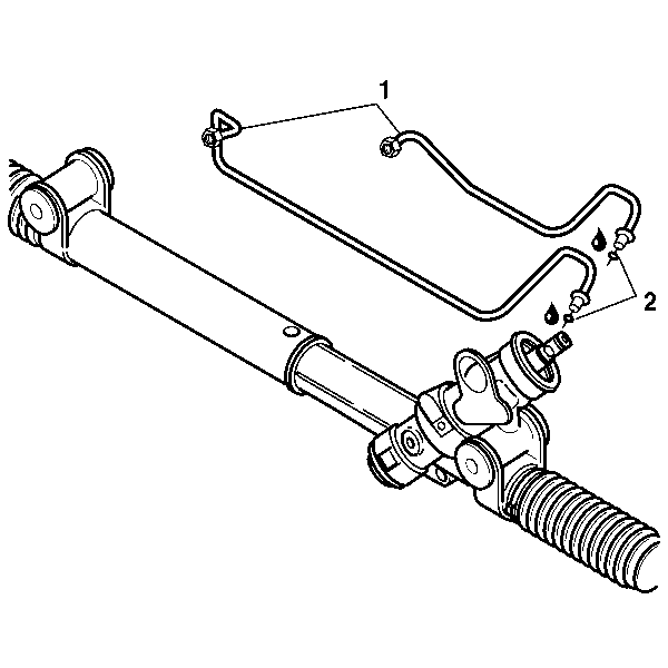
- Inspect the cylinder lines (1) for the following items:
- Replace the parts as needed.
- Lubricate and install the O-rings seals (2) onto the cylinder lines (1).
- Place the smaller cylinder line (2) into the valve housing (3).
- Place the other end of the cylinder line at the gear tube end (4).
- Place the larger cylinder line (2) into the valve housing (3).
- Place the other end of the cylinder line at the gear tube end (4).
- Place the cylinder line retaining plate (2) over the cylinder line beads at the valve end.
- Install the TORX® screw (1) into the cylinder line retaining plate (2) and tighten using an E 8 socket.
- Tighten both cylinder line nuts (3) at the cylinder end.
| • | Cracks |
| • | Dents |
| • | Damage to the threads |
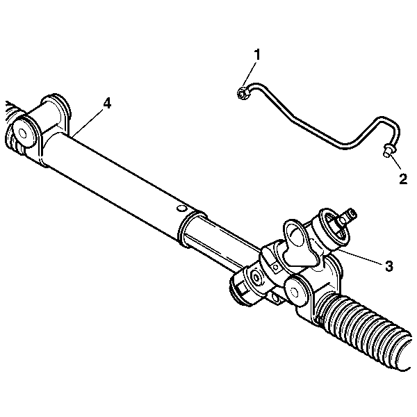
Important: You must install the smaller cylinder line into the valve housing (3) first.
Important: Hold the smaller cylinder line (2) in place . Do not torque the cylinder line nut (1).
Finger tighten the cylinder line nut (1) on the smaller cylinder line.
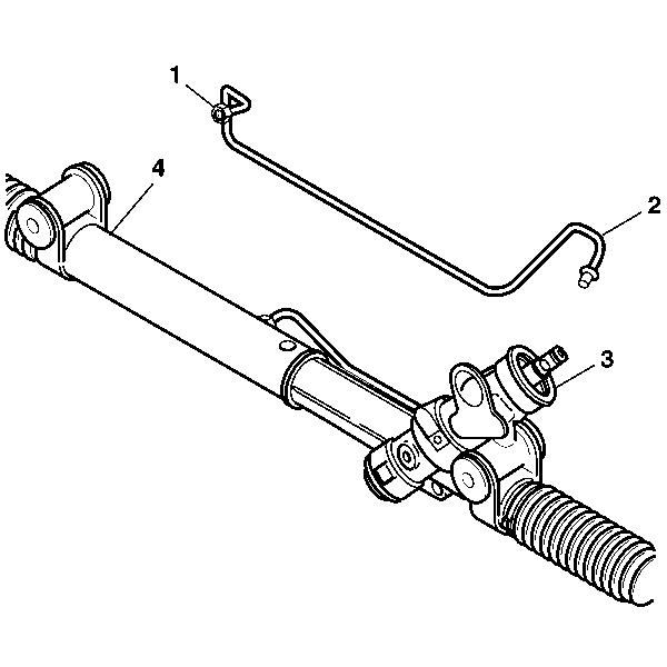
Important: You must install the larger cylinder line into the valve housing (3) first.
Important: Hold the larger cylinder line (2) in place. Do not torque the cylinder line nut (1).
Finger tighten the cylinder line nut (1) on the larger cylinder line.
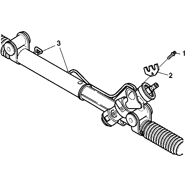
Notice: Refer to Fastener Notice in the Preface section.
Tighten
Tighten the screw to 12 N·m (106 lb in).
Tighten
Tighten the nuts to 32 N·m (24 lb ft).
