Circuit Description
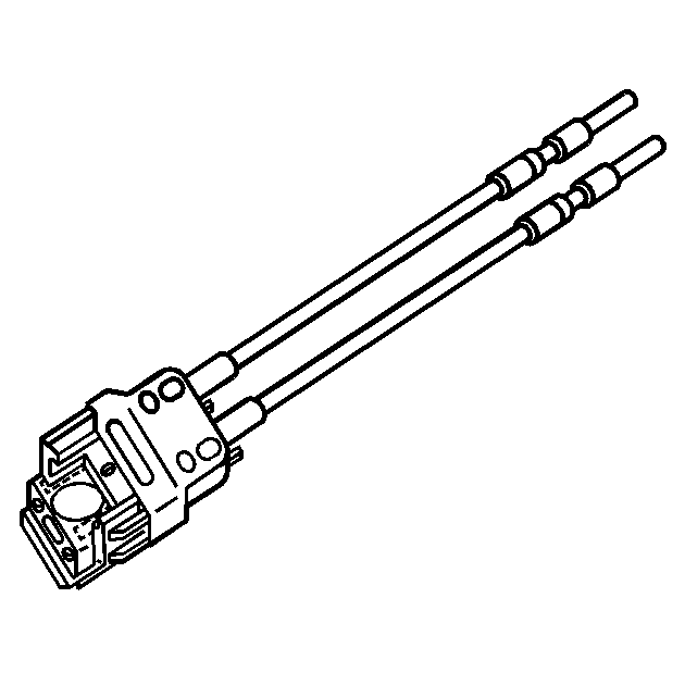
The secondary air injection (AIR) system is designed to reduce exhaust emissions after initial engine start-up. This occurs when coolant start up temperature and intake air temperature (IAT) are at the conditions listed below. The AIR pump will operate for less than 25 seconds. The powertrain control module (PCM) commands the AIR system ON by simultaneously supplying a ground to the AIR pump relay and the AIR solenoid relay . When commanded ON the AIR pump forces fresh air through the electronic shut-off valve and into the exhaust manifold, accelerating catalyst operation. When the AIR system is inactive, the electronic shut-off valve prevents airflow in both directions. The PCM will run the AIR diagnostic passive test only on ignition cycles when the pump is commanded ON. If this test passes, then no active test will run. If the passive test fails, or is inconclusive, the active test will run later in the ignition cycle. At that time the PCM runs a maximum of two 3 second active tests, monitoring the heated oxygen sensor (HO2S) 1 voltage, expecting a drop below 150 mV. When the PCM detects an insufficient HO2S 1 response, DTC P0410 will set.
Conditions for Running the DTC
| • | DTCs P0105, P0107, P0108, P0112, P0113, P0122, P0123, P0130, P0131, P0132, P0133, P0134, P0171, P0172, P0300, P0301-P0304, P0341, P0506, P0507, P0601, P0602 are not set. |
| • | The AIR system is commanded ON for more than 20 seconds. |
| • | The IAT is between 1-151°C (32-302°F). |
| • | The engine coolant temperature (ECT) is between 5-114°C (41-230°F). |
| • | The start up ECT is between 3-50°C (37-122°F). |
| • | The battery voltage is more than 11 volts. |
| • | The engine run time is more than 200 seconds. |
| • | The vehicle is operating in fuel trim cells 16 or 17. |
| • | The throttle position (TP) change is less than 5 percent. |
| • | The manifold absolute pressure (MAP) is less than 30 kPa. |
| • | The engine speed is more than 1,150 RPM. |
Conditions for Setting the DTC
The HO2S voltage parameter does not decrease to less than 150 mV for 1 second during a 3 second active test, for 2 consecutive active tests.
Action Taken When the DTC Sets
| • | The control module illuminates the malfunction indicator lamp (MIL) on the second consecutive ignition cycle that the diagnostic runs and fails. |
| • | The control module records the operating conditions at the time the diagnostic fails. The first time the diagnostic fails, the control module stores this information in the Failure Records. If the diagnostic reports a failure on the second consecutive ignition cycle, the control module records the operating conditions at the time of the failure. The control module writes the operating conditions to the Freeze Frame and updates the Failure Records. |
Conditions for Clearing the MIL/DTC
| • | The control module turns OFF the malfunction indicator lamp (MIL) after 3 consecutive ignition cycles that the diagnostic runs and does not fail. |
| • | A current DTC, Last Test Failed, clears when the diagnostic runs and passes. |
| • | A history DTC clears after 40 consecutive warm-up cycles, if no failures are reported by this or any other emission related diagnostic. |
| • | Clear the MIL and the DTC with a scan tool. |
Diagnostic Aids
| • | An intermittent may be caused by any of the following conditions: |
| - | Low system airflow |
| - | Excessive exhaust system back-pressure |
| - | Pinched, restricted, split, or damaged pipes/hoses |
| - | Restrictions in the AIR pump inlet hose |
| - | Pitted contacts in the AIR pump relay, AIR solenoid relay--Tap on the AIR pump relay or AIR solenoid relay to attempt to duplicate an intermittent condition. |
| - | Heat damage to the AIR outlet hose may indicate an shut-off valve failure |
| - | Yellow tinted water in the AIR pump may indicate an shut-off valve failure |
| - | Water or debris ingested into the AIR pump |
| - | Observe the Freeze Frame/Failure Records to aid in conditions of setting DTC P0410. |
| • | Thoroughly inspect any circuits that are suspected of causing the intermittent condition. Refer to Testing for Intermittent Conditions and Poor Connections in Wiring Systems. |
| • | If a repair is necessary, refer to Wiring Repairs or Connector Repairs in Wiring Systems. |
Test Description
The numbers below refer to the step numbers on the diagnostic table.
-
This step determines if excessive resistance on the supply voltage circuit between the AIR fuse and the AIR pump relay is the cause for an inoperative AIR pump. Two ohms of resistance on this circuit can prevent the AIR pump from running.
-
This step determines if excessive resistance on the AIR pump relay circuit and PCM driver is the cause for an inoperative AIR pump relay. The test lamp in series is intended to generate a electrical load on this circuit. 90 ohms of resistance on this circuit can prevent the AIR pump relay from operating.
-
This step determines if excessive resistance on the supply circuit is the cause for an inoperative AIR pump. Two ohms of resistance on this circuit can prevent the AIR pump from running.
-
This step determines if excessive resistance on the ground circuit is the cause for an inoperative AIR pump. Two ohms of resistance on this circuit can prevent the AIR pump from running.
-
This step determines if the AIR system is operating normally.
Step | Action | Values | Yes | No | ||||
|---|---|---|---|---|---|---|---|---|
Schematic Reference: Engine Controls Schematics Connector End View Reference: Powertrain Control Module Connector End Views or Engine Controls Connector End Views | ||||||||
1 | Did you perform the Diagnostic System Check-Engine Controls? | -- | Go to Step 2 | |||||
2 |
Does the AIR pump run continuously? | -- | Go to Step 3 | Go to Step 4 | ||||
3 | Remove the AIR pump relay. Refer to Relay Replacement in Wiring Systems. Does the AIR pump continue to operate? | -- | Go to Step 52 | Go to Step 5 | ||||
4 |
Important: The AIR pump has an internal circuit breaker to protect the pump from overheating. Intermittent AIR pump operation during testing may be normal.
Does the AIR pump turn ON and OFF when commanded with a scan tool? | -- | Go to Step 19 | Go to Step 6 | ||||
5 |
Does the test lamp illuminate? | -- | Go to Step 38 | Go to Step 54 | ||||
6 |
Is the fuse open? | -- | Go to Step 34 | Go to Step 7 | ||||
7 | Probe both test points of the AIR SOL fuse at the underhood fuse block. Does the test lamp illuminate at both test points? | -- | Go to Step 8 | Go to Step 31 | ||||
8 |
Does the test lamp illuminate? | -- | Go to Step 9 | Go to Step 46 | ||||
Is the voltage drop less than the specified value? | 0.6 V | Go to Step 10 | Go to Step 46 | |||||
10 |
Does the test lamp illuminate? | -- | Go to Step 11 | Go to Step 48 | ||||
11 | Measure the resistance of the ignition 1 voltage circuit from the AIR relay connector to the AIR SOL fuse. Is the resistance less than the specified value? | 10 ohms | Go to Step 12 | Go to Step 48 | ||||
12 |
Does the test lamp turn ON and OFF when commanded with a scan tool? | -- | Go to Step 13 | Go to Step 30 | ||||
Measure the resistance of the AIR pump relay control circuit from the AIR pump relay connector to the PCM connector with a DMM. Refer to Circuit Testing in Wiring Systems. Is the resistance less than the specified value? | 10 ohms | Go to Step 14 | Go to Step 47 | |||||
14 |
Does the AIR pump turn ON? | -- | Go to Step 42 | Go to Step 15 | ||||
15 |
Does the test lamp illuminate? | -- | Go to Step 16 | Go to Step 49 | ||||
16 | Connect a test lamp between the AIR pump supply voltage circuit and the AIR pump ground circuit at the AIR pump harness connector. Does the test lamp illuminate? | -- | Go to Step 17 | Go to Step 50 | ||||
Is the voltage drop less than the specified value? | 0.6 V | Go to Step 18 | Go to Step 49 | |||||
Measure the voltage drop from the AIR pump ground circuit of the AIR pump, to a good ground with a DMM. Refer to Measuring Voltage Drop in Wiring Systems. Is the voltage drop less than the specified value? | 0.6 V | Go to Step 43 | Go to Step 50 | |||||
|
Important: Under certain conditions, a faulty oxygen sensor (O2) may set this DTC without setting an O2 DTC. O2 sensor voltage will typically decrease to approximately 10 mV or less while the vehicle is in Decel Fuel Cutoff, or approximately 30 mV or less while idling with a large intake air leak, such as a disconnected brake booster vacuum hose.
Does the HO2S 1 voltage parameter decrease below the specified value? | 75 mV | Go to Diagnostic Aids | Go to Step 20 | |||||
20 |
Is a pressurized airflow present at the AIR pump outlet hose? | - | Go to Step 21 | Go to Step 40 | ||||
21 |
Does the test lamp illuminate? | - | Go to Step 22 | Go to Step 47 | ||||
22 |
Does the test lamp illuminate? | -- | Go to Step 23 | Go to Step 25 | ||||
23 | Measure the resistance of the following circuits:
Is the resistance on each circuit less than the specified amount? | 10 ohms | Go to Step 24 | Go to Step 47 | ||||
24 |
Is an audible exhaust sound heard at the inlet of the AIR shut-off valve, each time the circuit is connected to a ground? | -- | Go to Intermittent Conditions | Go to Step 57 | ||||
25 |
Does the test lamp illuminate? | -- | Go to Step 26 | Go to Step 53 | ||||
26 |
Does the test lamp turn ON and OFF? | -- | Go to Step 28 | Go to Step 27 | ||||
27 | Does the test lamp remain illuminated? | -- | Go to Step 38 | Go to Step 30 | ||||
28 | Measure the resistance of the AIR solenoid relay control circuit from the AIR solenoid relay connector to the PCM connector with a DMM. Refer to Circuit Testing in Wiring Systems. Is the resistance less than the specified value? | 10 ohms | Go to Step 29 | Go to Step 47 | ||||
29 |
Important: The fuse rating shall not exceed the load rating of the jumper wire.
Does the test lamp illuminate? | -- | Go to Step 45 | Go to Step 51 | ||||
30 | Test the AIR relay control circuit for an open, short to voltage, or short to ground. Refer to Circuit Testing and Wiring Repairs in Wiring Systems. Did you find and correct the condition? | -- | Go to Step 59 | Go to Step 44 | ||||
31 | Does the test lamp illuminate at one side of the AIR SOL fuse? | -- | Go to Step 32 | Go to Step 53 | ||||
32 |
Did you find and correct the condition? | -- | Go to Step 60 | Go to Step 33 | ||||
33 | Measure the resistance of the AIR solenoid. Is the resistance within the specified range? | 4-8 ohms | Go to Step 39 | Go to Step 57 | ||||
34 |
Did you find and correct the condition? | -- | Go to Step 60 | Go to Step 35 | ||||
35 | Test the AIR pump supply voltage circuit for a short to voltage. Refer to Wiring Repairs and Circuit Testing in Wiring Systems. Did you find and correct the condition? | -- | Go to Step 59 | Go to Step 36 | ||||
36 | Test the AIR pump supply voltage circuit for a short to ground. Refer to Wiring Repairs and Circuit Testing in Wiring Systems. Did you find and correct the condition? | -- | Go to Step 60 | Go to Step 37 | ||||
37 |
Does the AIR pump turn ON with a scan tool? | -- | Go to Testing for Intermittent Conditions and Poor Connections in Wiring Systems | Go to Step 56 | ||||
38 | Test the AIR relay control circuit for a short to ground. Refer to Wiring Repairs and Circuit Testing in Wiring Systems. Did you find and correct the condition? | -- | Go to Step 59 | Go to Step 44 | ||||
39 |
Did you find and correct the condition? | -- | Go to Step 60 | Go to Testing for Intermittent Conditions and Poor Connections in Wiring Systems | ||||
40 | Inspect the AIR pump outlet hose for the following conditions:
Did you find and correct the condition? | -- | Go to Step 60 | Go to Step 41 | ||||
41 | Inspect for a restriction at the following locations:
Did you find and correct the condition? | -- | Go to Step 60 | Go to Step 56 | ||||
42 | Test for an intermittent and for a poor connection at the AIR pump relay. Refer to Testing for Intermittent Conditions and Poor Connections and Connector Repairs in Wiring Systems. Did you find and correct the condition? | -- | Go to Step 59 | Go to Step 54 | ||||
43 | Test for an intermittent and for a poor connections at the AIR pump. Refer to Testing for Intermittent Conditions and Poor Connections and Connector Repairs in Wiring Systems. Did you find and correct the condition? | -- | Go to Step 59 | Go to Step 56 | ||||
44 | Test for shorted connections or for a poor connection at the powertrain control module (PCM). Refer to Testing for Intermittent Conditions and Poor Connections and Connector Repairs in Wiring Systems. Did you find and correct the condition? | -- | Go to Step 59 | Go to Step 58 | ||||
45 | Test for an intermittent and for a poor connection at the AIR solenoid relay. Refer to Testing for Intermittent Conditions and Poor Connections and Connector Repairs in Wiring Systems. Did you find and correct the condition? | -- | Go to Step 60 | Go to Step 55 | ||||
46 | Repair the open or high resistance in the battery positive circuit between the AIR pump fuse and the AIR pump relay. Refer to Wiring Repairs in Wiring Systems. Did you complete the repair? | -- | Go to Step 60 | -- | ||||
47 | Repair the circuit with the open or high resistance. Refer to Wiring Repairs in Wiring Systems. Did you complete the repair? | -- | Go to Step 60 | -- | ||||
48 | Repair the open or high resistance in the ignition 1 voltage circuit. Refer to Wiring Repairs in Wiring Systems. Did you complete the repair? | -- | Go to Step 60 | -- | ||||
49 | Repair the open or high resistance in the AIR pump supply voltage circuit. Refer to Wiring Repairs in Wiring Systems. Did you complete the repair? | -- | Go to Step 60 | -- | ||||
50 | Repair the open or high resistance in the AIR pump ground circuit. Refer to Wiring Repairs in Wiring Systems. Did you complete the repair? | -- | Go to Step 60 | -- | ||||
51 | Repair the open or high resistance in the AIR solenoid supply voltage circuit. Refer to Wiring Repairs in Wiring Systems. Did you complete the repair? | -- | Go to Step 60 | -- | ||||
52 |
Did you complete the repair? | -- | Go to Step 59 | -- | ||||
53 | Replace the underhood fuse block. Refer to Underhood Electrical Center or Junction Block Replacement in Wiring Systems. Did you complete the replacement? | -- | Go to Step 60 | -- | ||||
54 | Replace the AIR pump relay. Refer to Relay Replacement in Wiring Systems. Did you complete the replacement? | -- | Go to Step 59 | -- | ||||
55 | Replace the AIR solenoid relay. Refer to Relay Replacement in Wiring Systems. Did you complete the replacement? | -- | Go to Step 60 | -- | ||||
56 | Replace the AIR pump. Refer to Secondary Air Injection Pump Replacement . Did you complete the replacement? | -- | Go to Step 59 | -- | ||||
57 | Replace the AIR electronic shut-off valve assembly. Refer to Secondary Air Injection Solenoid Valve Replacement . Did you complete the replacement? | -- | Go to Step 60 | -- | ||||
58 | Replace the PCM. Refer to Powertrain Control Module Replacement . Did you complete the replacement? | -- | Go to Step 59 | -- | ||||
59 |
Does the AIR pump turn ON and OFF when commanded with a scan tool? | -- | Go to Step 60 | Go to Step 2 | ||||
60 |
Did the DTC fail this ignition? | -- | Go to Step 2 | Go to Step 61 | ||||
61 | Observe the Capture Info with a scan tool. Are there any DTCs that have not been diagnosed? | -- | System OK | |||||
