When the gear selector lever is in the Park (P) position, fluid is drawn into the pump through the transmission fluid filter assembly, from the transmission fluid pan assembly. Line pressure is then directed to the following valves:
FLUID PRESSURE DIRECTED IN PREPARATION FOR A SHIFT
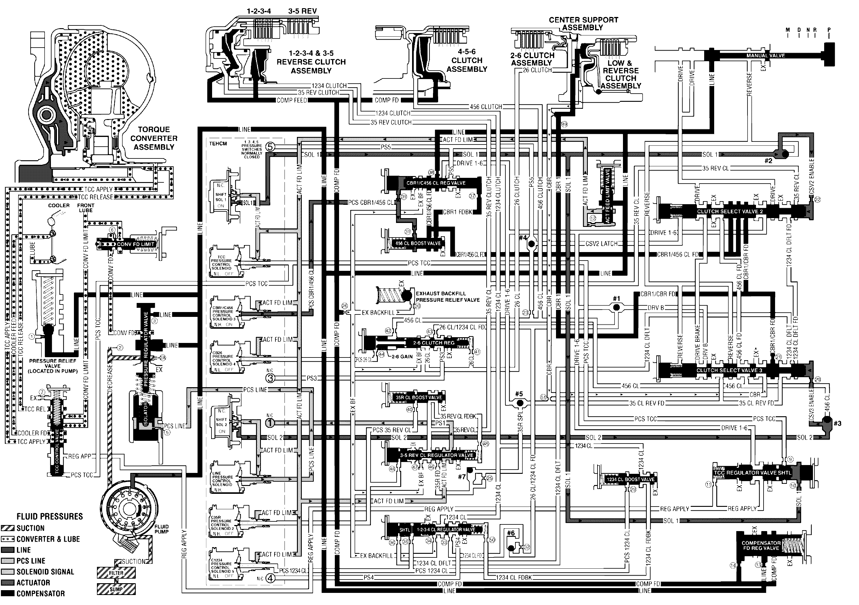
Manual Valve
Mechanically controlled by the gear selector lever, the manual valve is in the Park (P) position and prevents line pressure from the pressure regulator valve from entering the reverse and drive circuits.
CBR1/C456 Pressure Control (PC) Solenoid 3
The CBR1/C456 PCS is energized (HIGH) allowing actuator feed limit fluid to enter the PCS CBR1/C456 CL fluid circuit. PCS CBR1/C456 CL fluid is then routed through orifice #31 to the 4-5-6 clutch boost valve and through orifice #39 to the CBR1/ C456 clutch regulator valve.
CBR1/C456 Clutch Regulator Valve
PCS CBR1/C456 CL fluid at the CBR1/C4-5-6 clutch regulator valve moves the valve against CBR1/C4-5-6 clutch regulator spring force and CBR1/FDBK fluid. This allows line pressure to pass through the valve and enter the CBR1/456CL FD circuit. CBR1/456CL FD is then routed to Clutch Select Valve 2.
Shift Solenoid 1
Shift solenoid 1 is energized (ON) allowing actuator feed limit fluid to enter the solenoid 1 circuit. Solenoid 1 fluid is routed to the #2 ball check valve and through orifice #10 to the TCC regulator valve and shuttle valve (SHTL).
TCC Regulator Valve and Shuttle Valve
Solenoid 1 fluid is routed to the TCC regulator valve and shuttle valve and moves the valve against TCC regulator valve spring force.
#2 Ball Check Valve
Solenoid 1 fluid seats the #2 ball check valve against the reverse fluid passage and fluid is forced through orifice #22 into the CSV2 enable fluid circuit.
Clutch Select Valve 2
CSV2 enable fluid is routed to the clutch select valve 2 and moves the valve against clutch select valve 2 spring force. This allows CBR1/456 CL FD fluid to pass through the valve and enter the CBR1/CBR FD circuit. CBR1/CBR FD fluid is then routed: to clutch select valve 3, into the CBR1 fluid circuit and, through orifice #49 where it enters the CBR fluid circuit and an exhaust passage at the clutch select valve 3 (this fluid is intended to keep the low and reverse clutch full of fluid but not pressurized). CBR1 fluid is then routed to the low & reverse clutch assembly in preparation for a shift into low or reverse gear.
Shift Solenoid 2
Shift solenoid 2 is energized (ON) allowing actuator feed limit fluid to enter the solenoid 2 fluid circuit and is then routed to the #3 ball check valve.
3-5 Reverse Clutch Regulator Valve
Actuator feed limit fluid is routed through the valve and into the PS1 fluid passage. PS1 fluid is then sent to the normally closed #1 pressure switch and opens the switch.
#3 Ball Check Valve
Solenoid 2 fluid seats the #3 ball check valve against 456 CL fluid passage and fluid is forced through orifice #20 into the CSV3 enable fluid circuit. CSV3 enable fluid is then routed to the clutch select valve 3.
Clutch Select Valve #3
CSV3 enable fluid moves the clutch select valve 3 against clutch select valve 3 spring force. CBR fluid at the clutch select valve 3 passes through the valve and exhausts.
Park - Engine Running