Headlamp Leveling Control Module Replacement LWB
Removal Procedure
- Disconnect the battery ground cable. Refer to Battery Negative Cable Disconnection and Connection.
- Remove the coolant recovery reservoir. Refer to Coolant Recovery Reservoir Replacement.
- Remove the headlamp assembly. Refer to Headlamp Replacement.
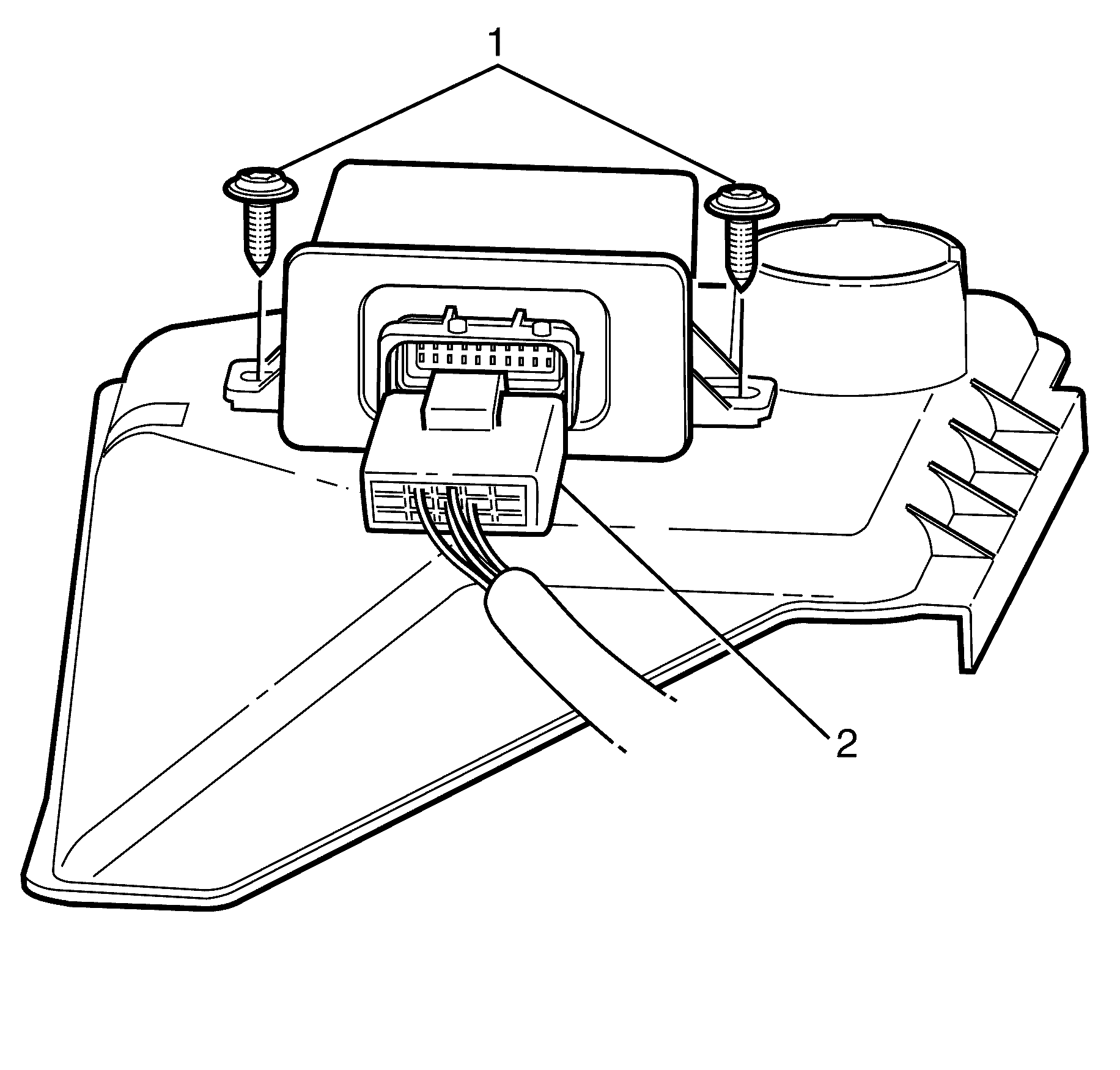
- Disconnect the headlamp levelling module electrical connector (2).
- Remove the headlamp levelling module retaining torx screws (1).
- Remove the headlamp levelling module.
Caution: Refer to Battery Disconnect Caution in the Preface section.
Caution: The high intensity discharge system produces high voltage and current.
To reduce the risk of severe shocks and burns:
• Never open the high intensity discharge system ballast or the
arc tube assembly starter. • Never probe between the high intensity discharge system ballast
output connector and the arc tube assembly.
Caution: The high intensity discharge system produces high voltage and current. In order to reduce the risk of severe shocks and burns, the battery negative cable must be disconnected any time service work is being performed on or around the high intensity discharge system.
Installation Procedure
- Install the headlamp levelling module.
- Connect the headlamp levelling module electrical connector (2).
- Install the headlamp levelling module retaining torx screws (1).
- Install the coolant recovery reservoir. Refer to Coolant Recovery Reservoir Replacement.
- Connect the battery ground cable. Refer to Battery Negative Cable Disconnection and Connection.
- Check all vehicle lights for correct operation.

Notice: Refer to Fastener Notice in the Preface section.
Tighten
Tighten the screws to 4.0 N·m (35 lb in).
Headlamp Leveling Control Module Replacement SWB
Removal Procedure
- Disconnect the battery ground cable. Refer to Battery Negative Cable Disconnection and Connection.
- Raise and support the vehicle. Refer to Lifting and Jacking the Vehicle.
- Remove the headlamp levelling sensor linkage retaining bolt (1).
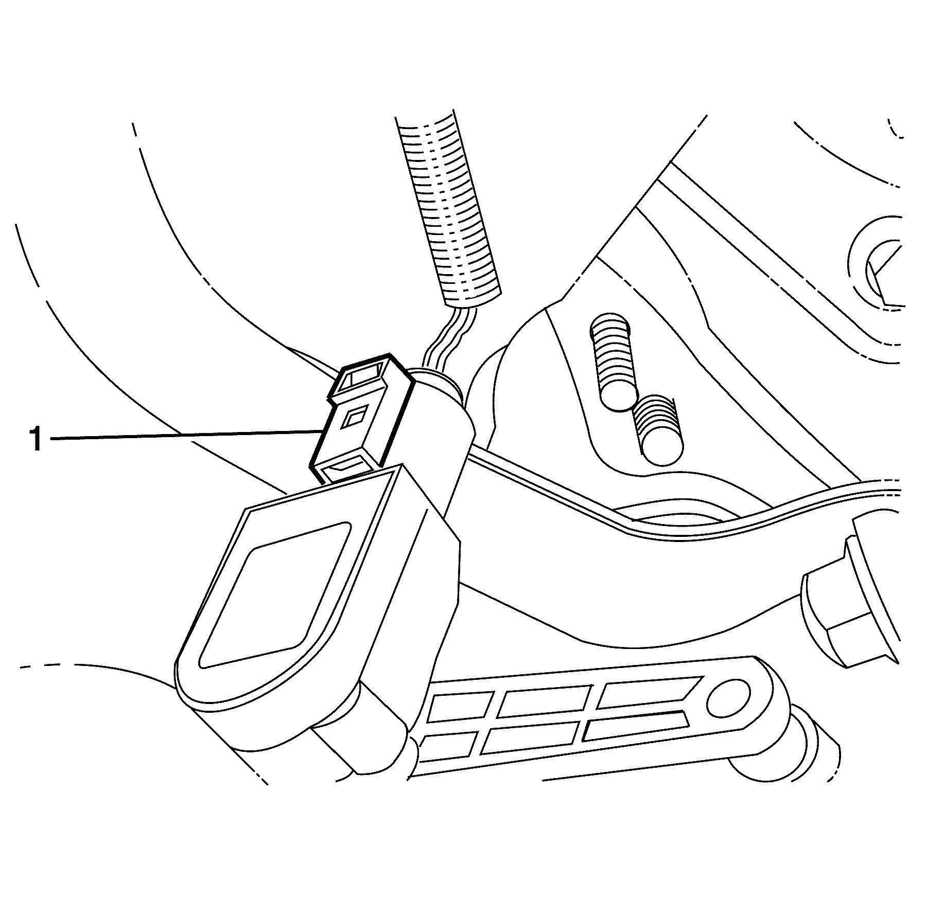
- Disconnect the headlamp levelling sensor electrical connector (1).
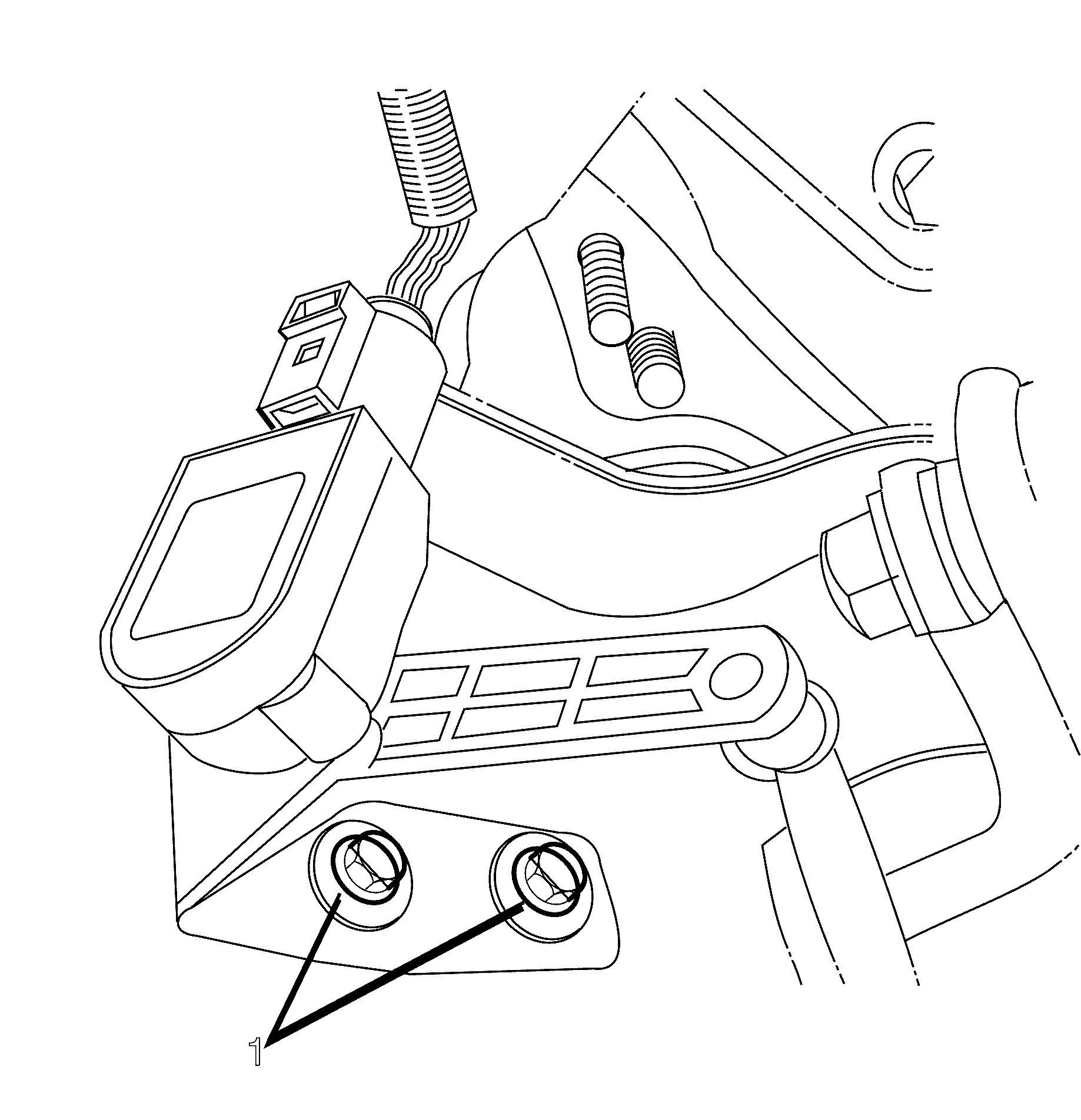
- Remove the head lamp levelling sensor retaining bolts.
- Remove the head lamp levelling sensor.
Caution: Refer to Battery Disconnect Caution in the Preface section.
Caution: The high intensity discharge system produces high voltage and current.
To reduce the risk of severe shocks and burns:
• Never open the high intensity discharge system ballast or the
arc tube assembly starter. • Never probe between the high intensity discharge system ballast
output connector and the arc tube assembly.
Caution: The high intensity discharge system produces high voltage and current. In order to reduce the risk of severe shocks and burns, the battery negative cable must be disconnected any time service work is being performed on or around the high intensity discharge system.
Caution: Refer to Safety Glasses Caution in the Preface section.
Caution: Refer to Vehicle Lifting Caution in the Preface section.
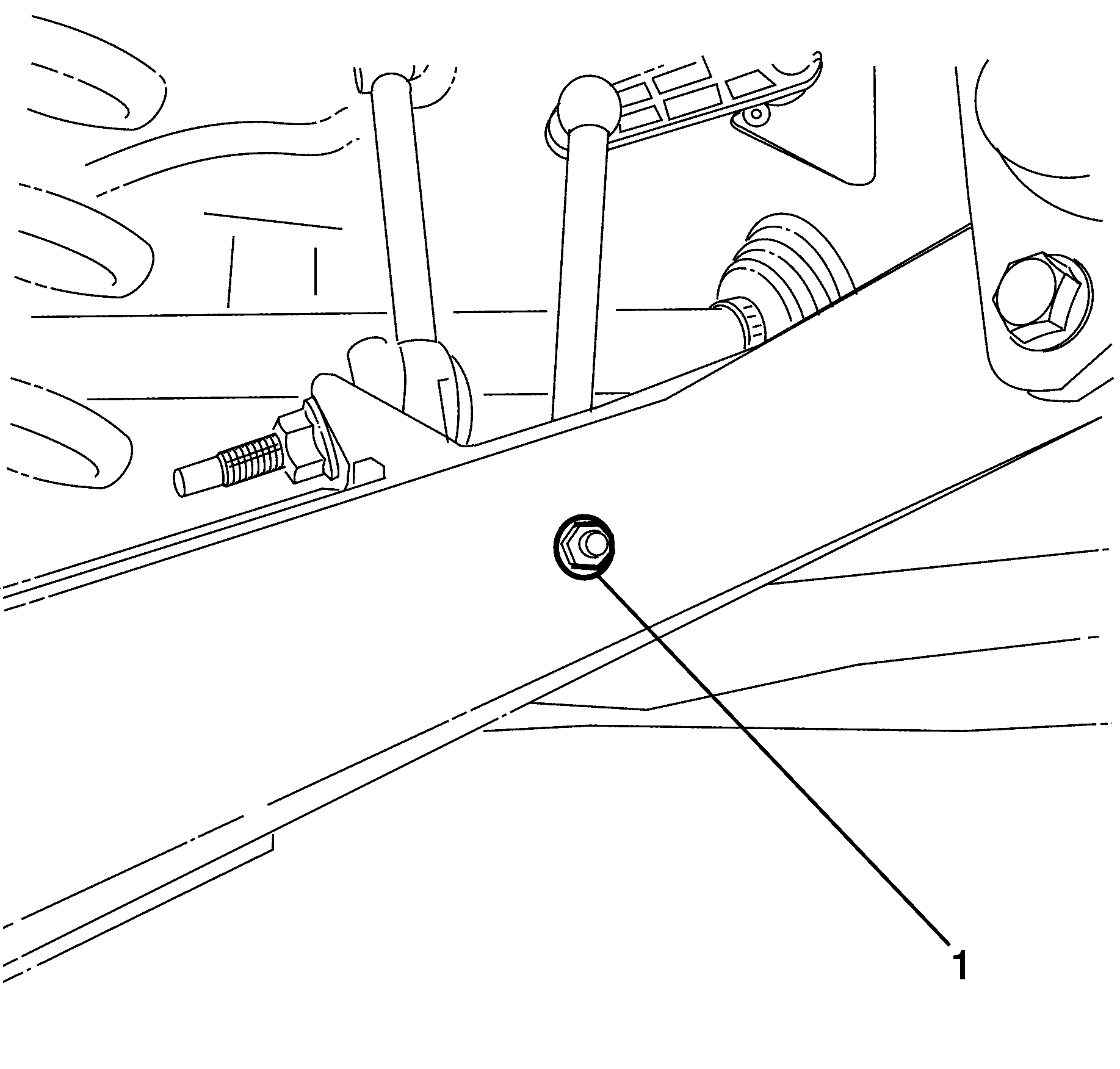
Important: The headlamp levelling linkages are not a serviceable item and should be replaced as a complete assembly.
Installation Procedure
- Install the head lamp levelling sensor.
- Install the head lamp levelling sensor retaining bolts.
- Connect the headlamp levelling sensor electrical connector (1).
- Install the head lamp levelling sensor linkage.
- Install the head lamp levelling sensor linkage retaining nut (1).
- Lower the vehicle. Refer to Lifting and Jacking the Vehicle.
- Connect the battery ground cable. Refer to Battery Negative Cable Disconnection and Connection.
- Check all vehicle lights for correct operation.

Notice: Refer to Fastener Notice in the Preface section.
Tighten
Tighten the bolts to 9.0 N·m (80 lb in).


Notice: Refer to Fastener Notice in the Preface section.
Tighten
Tighten the nut to 4.0 N·m (35 lb in).
Headlamp Leveling Control Module Replacement Front
Removal Procedure
- Disconnect the battery ground cable. Refer to Battery Negative Cable Disconnection and Connection.
- Raise and support the vehicle. Refer to Lifting and Jacking the Vehicle.
- Remove the air deflector. Refer to Front Air Deflector Replacement.
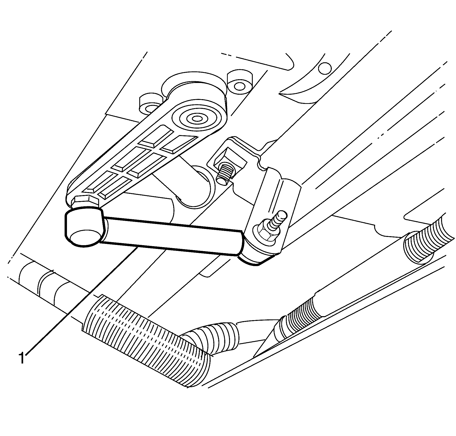
- Using a suitable tool, remove the headlamp levelling sensor linkage (1) from the front suspension sway bar linkage.
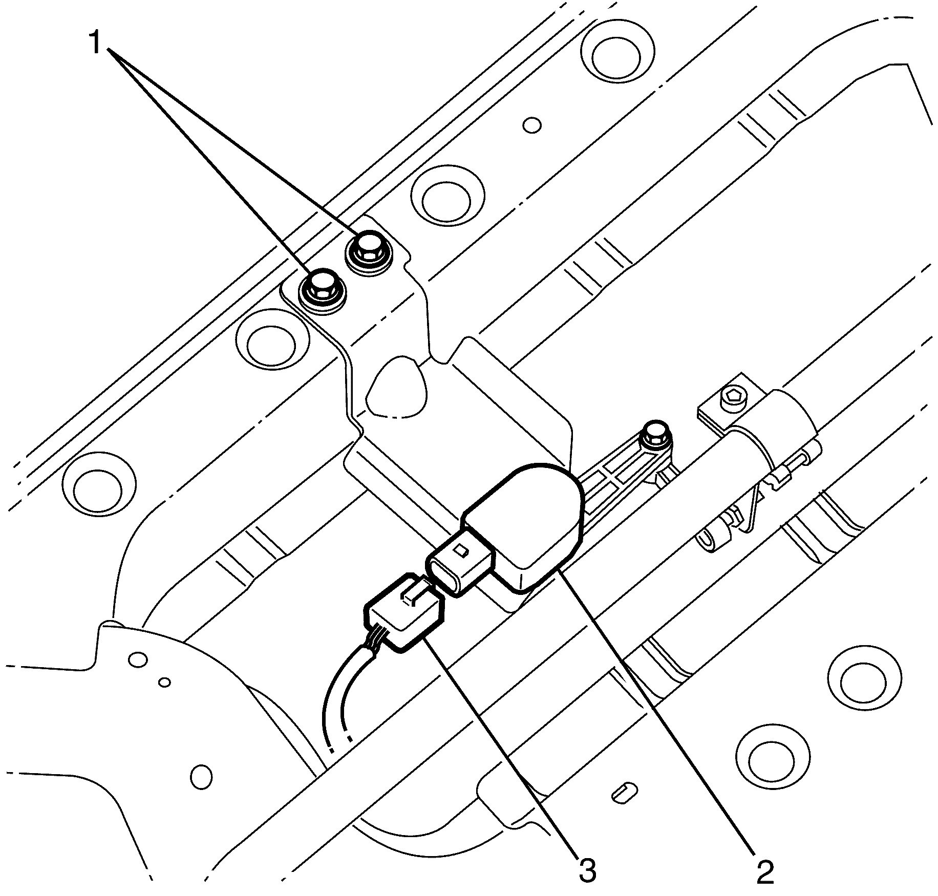
- Disconnect the headlamp levelling sensor electrical connector (3).
- Remove the headlamp levelling sensor retaining bolts (1).
- Remove the headlamp levelling sensor (2).
Caution: Refer to Battery Disconnect Caution in the Preface section.
Caution: The high intensity discharge system produces high voltage and current.
To reduce the risk of severe shocks and burns:
• Never open the high intensity discharge system ballast or the
arc tube assembly starter. • Never probe between the high intensity discharge system ballast
output connector and the arc tube assembly.
Caution: The high intensity discharge system produces high voltage and current. In order to reduce the risk of severe shocks and burns, the battery negative cable must be disconnected any time service work is being performed on or around the high intensity discharge system.
Caution: Refer to Safety Glasses Caution in the Preface section.
Caution: Refer to Vehicle Lifting Caution in the Preface section.
Installation Procedure
- Install the headlamp levelling sensor (2).
- Install the headlamp levelling sensor retaining bolts (1).
- Connect the headlamp levelling sensor electrical connector (3).
- Install the headlamp levelling sensor linkage to the sway bar linkage, listen for an audible click to confirm fitting.
- Install the air deflector. Refer to Front Air Deflector Replacement.
- Lower the vehicle. Refer to Lifting and Jacking the Vehicle.
- Connect the battery ground cable. Refer to Battery Negative Cable Disconnection and Connection.
- Check all vehicle lights for correct operation.

Notice: Refer to Fastener Notice in the Preface section.
Tighten
Tighten the bolts to 8.0 N·m (71 lb in).
