For 1990-2009 cars only
Knee Bolster Replacement RHD
Removal Procedure
- Remove the insulator panel. Refer to Instrument Panel Insulator Panel Replacement - Right Side .
- Remove the Instrument Panel Outer Trim Cover. Refer to Instrument Panel Outer Trim Cover Replacement .
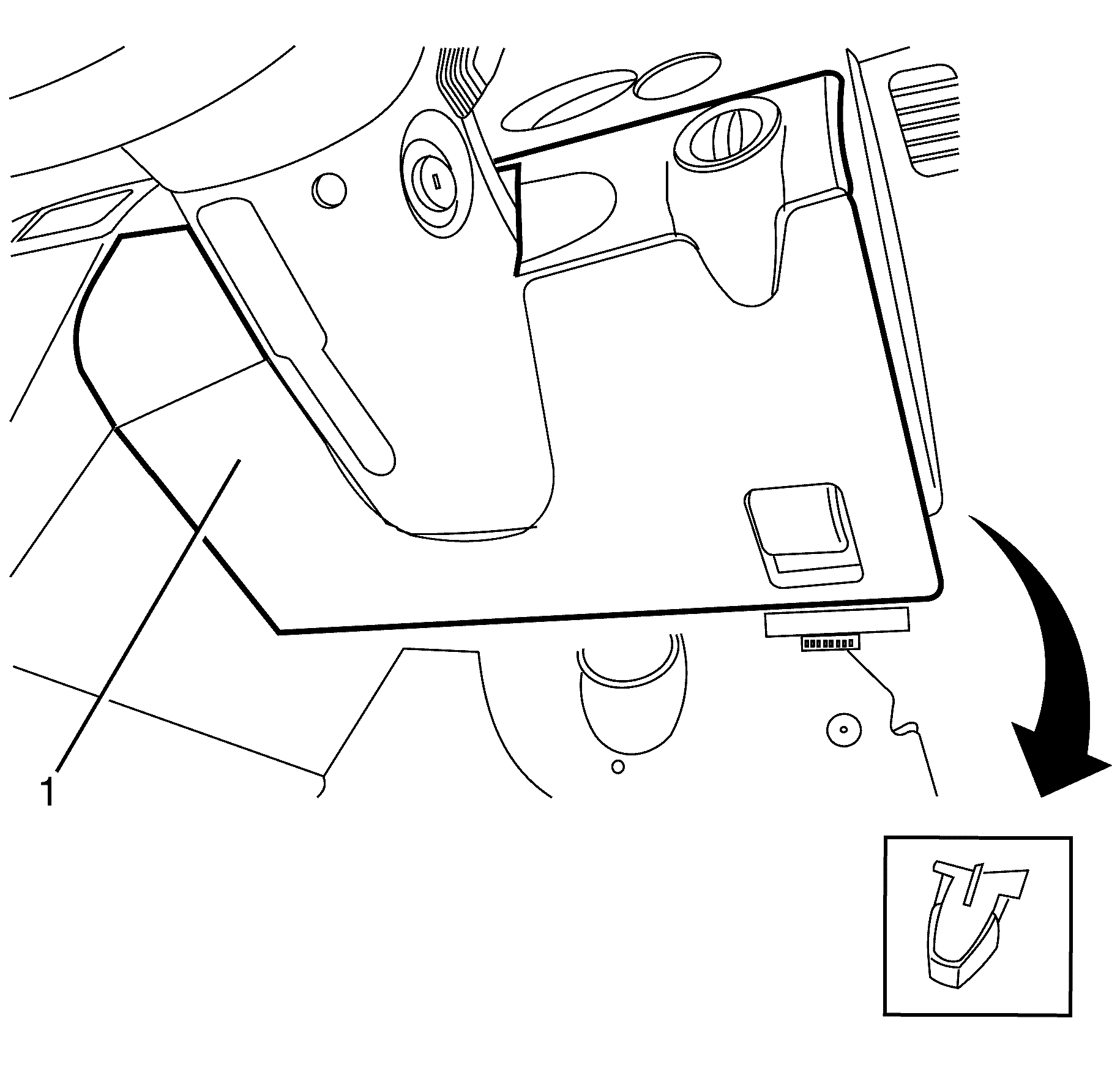
- Grasp the knee bolster assembly (1) and carefully pull downward to disengage the retaining clips.
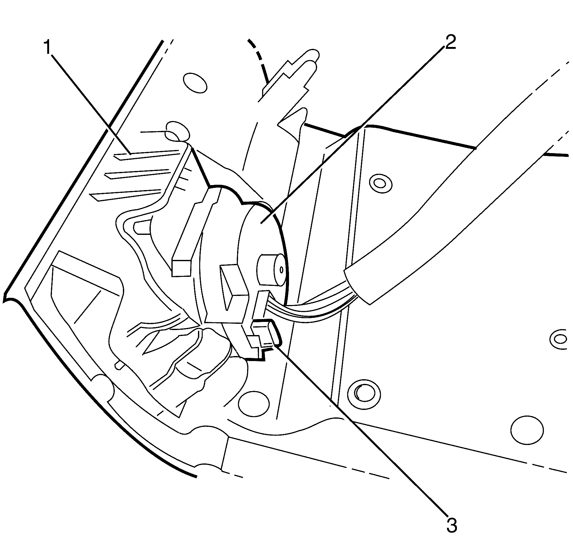
- Disconnect the headlamp switch (2) electrical connecter (3) from headlamp switch.
- Remove the knee bolster (1).

Important: When removing the knee bolster, care must be taken not to scratch the steering column cover. This can be achieved by slightly bending the knee bolster to avoid contact with the steering column.

Installation Procedure
- Connect the headlamp switch (2) electrical connector (3).
- Align the knee bolster (1) with the I/P pad.
- Install the knee bolster (1) to the I/P by engaging the retaining clips.
- Install the Instrument Panel Outer Trim Cover. Refer to Instrument Panel Outer Trim Cover Replacement .
- Install the insulator panel. Refer to Instrument Panel Insulator Panel Replacement - Right Side .
- Ensure all clips are located correctly.


Knee Bolster Replacement LHD
Removal Procedure
- Remove the insulator panel. Refer to Instrument Panel Insulator Panel Replacement - Left Side.
- Remove the Instrument Panel Outer Trim Cover. Refer to Instrument Panel Outer Trim Cover Replacement.
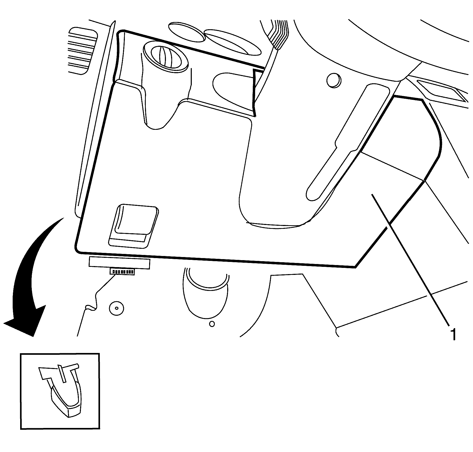
- Grasp the knee bolster assembly (1) and carefully pull downward to disengage the retaining clips.
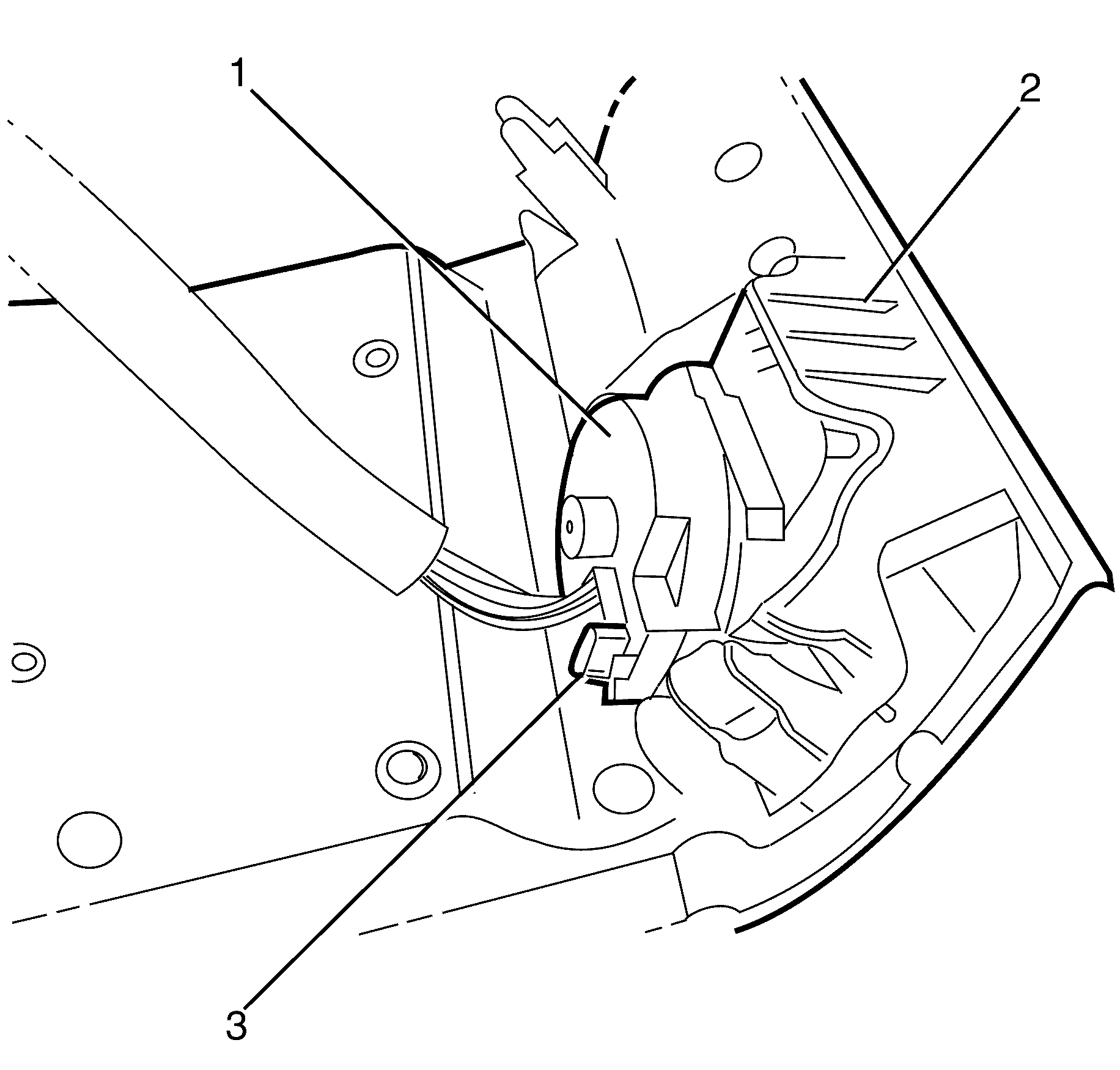
- Disconnect the headlamp switch (1) electrical connecter (3) from headlamp switch.
- Remove the knee bolster (2).

Important: When removing the knee bolster, care must be taken not to scratch the steering column cover. This can be achieved by slightly bending the knee bolster to avoid contact with the steering column.

Installation Procedure
- Connect the headlamp switch (1) electrical connector (3).
- Align the knee bolster (2) with the I/P pad.
- Install the knee bolster (1) to the I/P by engaging the retaining clips.
- Install the Instrument Panel Outer Trim Cover. Refer to Instrument Panel Outer Trim Cover Replacement.
- Install the insulator panel. Refer to Instrument Panel Insulator Panel Replacement - Left Side.
- Ensure all clips are located correctly.


