Automatic Transmission Shift Lock Control Actuator Replacement LHD 5L40
Removal Procedure
- Remove the floor shift control. Refer to Transmission Control Lever Knob Replacement.
- Using the manual override lever, shift the selector lever to the drive (D) position.
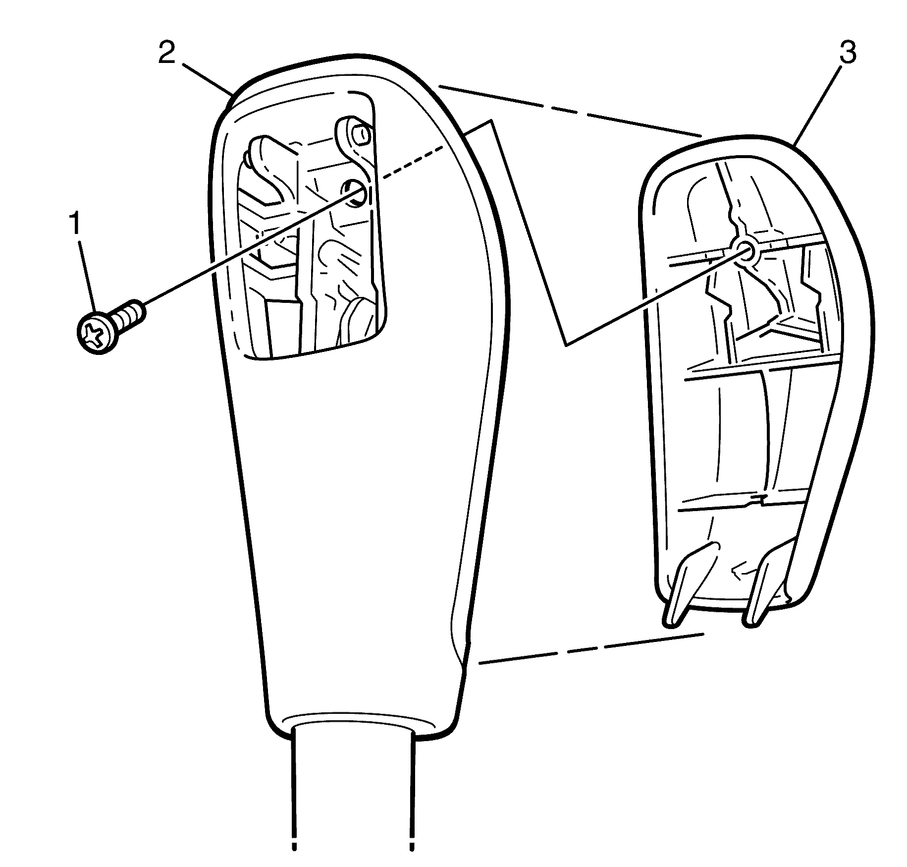
- Remove the selector knob to selector lever retaining screw (1).
- Remove the selector knob (3) from the selector lever (2).
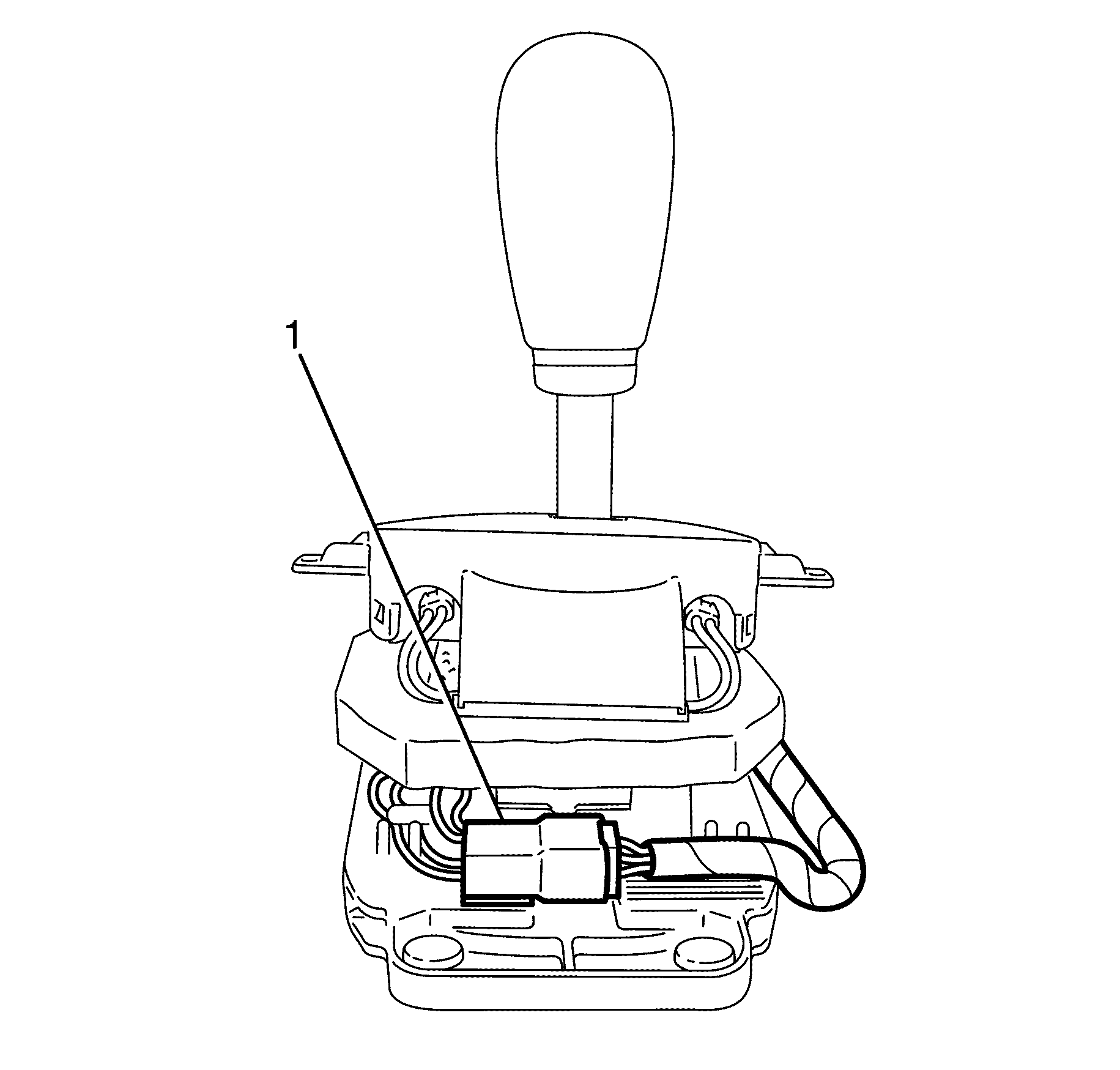
- Disconnect the wiring harness connector (1) from the rear of the selector assembly.
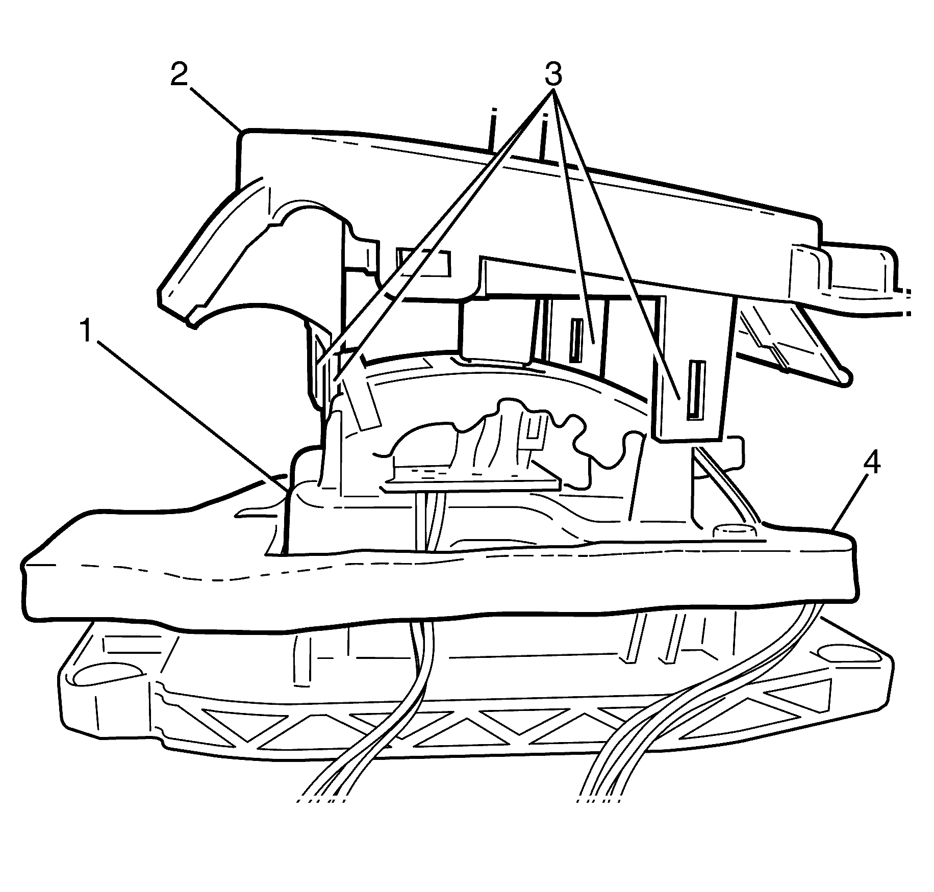
- Disconnect the selector lever housing (2) from the base (1) by depressing the four retaining tabs (3).
- Lift the shift lever housing assembly (2) from the base (1).
- Remove the insulator (4) from the base (1).
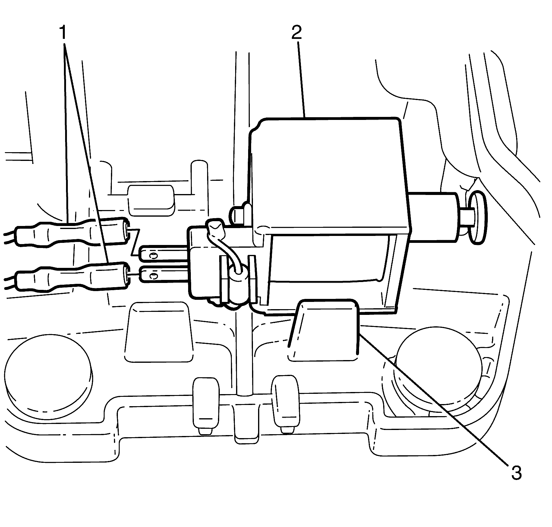
- Disconnect the solenoid wiring harness connector (1) from the shift lock solenoid (2).
- Disengage the solenoid retainer clip (3).
- Remove the solenoid (2).
- If necessary, remove the park lock micro switch retaining screw (2).
- Remove the micro switch (1) and wiring harness from the floor shift control base plate.
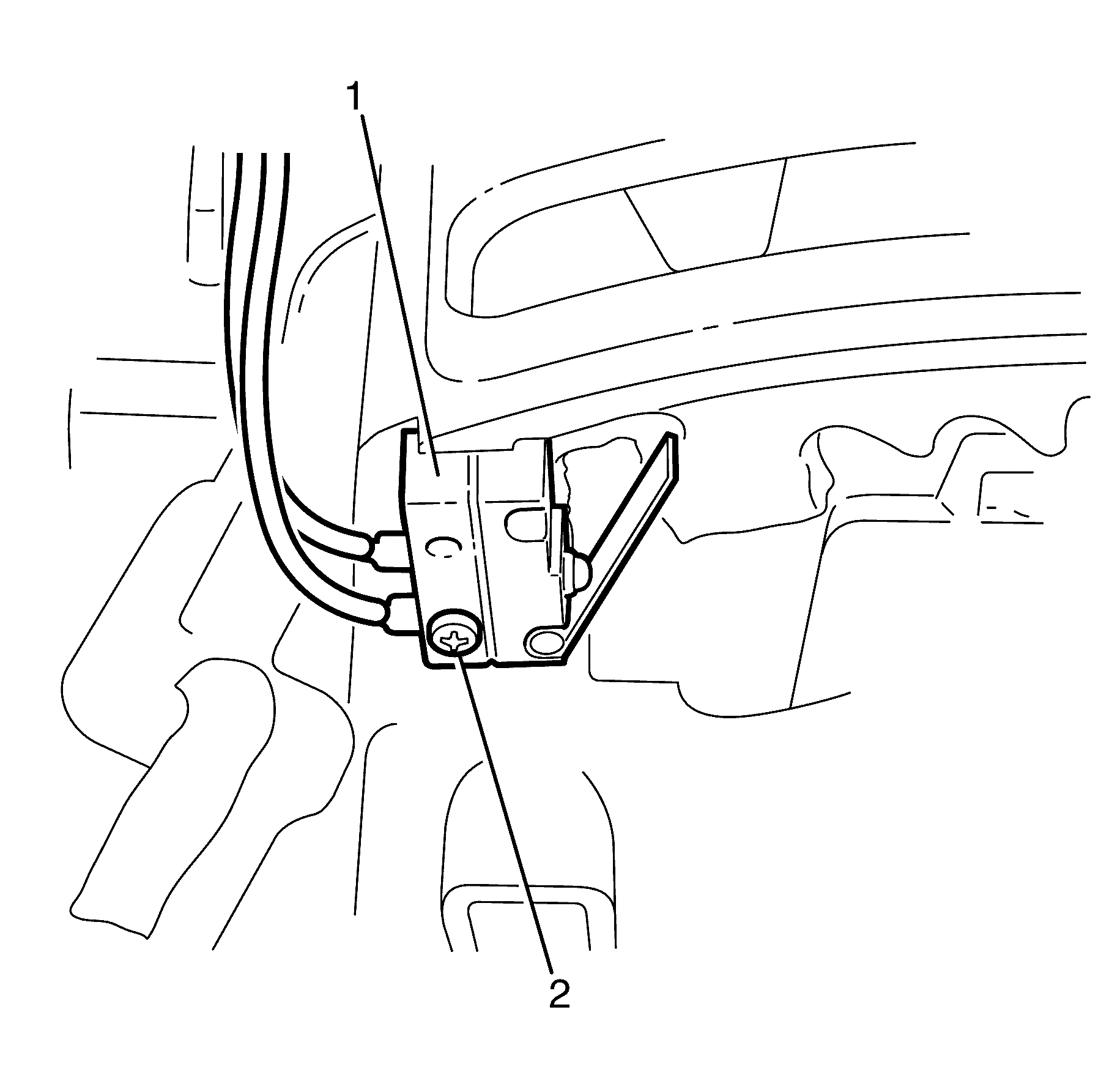
Important: After the solenoid is remove the lock tabs can be turned allowing access to micro switch screw.
Important: Note the position of the micro switch wiring harness routing for reassembly. The switches are incorporated into the wiring harness and cannot be serviced separately.
Installation Procedure
- If removed, install the micro switch (1) and wiring harness to the floor shift control base plate.
- Install the park lock micro switch retaining screw (2).
- Route the wiring harness insuring no contact with moving component and the wire is not stretched.
- Install the solenoid (2) into retaining clip (3).
- Connect the solenoid wiring harness connector (1) to the shift lock solenoid (2).
- Install the insulator (4) to the base (1).
- Connect the selector lever housing (1) to the base (2) by locking the four retaining tabs (3).
- Connect the wiring harness connector (1) to the rear of the selector assembly.
- Install the selector knob (3) to the selector lever (2)..
- Install the selector knob to selector lever retaining scew (1).
- Install the floor shift control. Refer to Transmission Control Lever Knob Replacement.

Notice: Refer to Fastener Notice in the Preface section.
Tighten
Tighten the screws to 0.5 N·m (4 lb in).


Tighten
Tighten the screw to 2 N·m (18 lb in).
Automatic Transmission Shift Lock Control Actuator Replacement LHD 6L80
Removal Procedure
- Remove the floor shift control. Refer to Floor Shift Control Knob Replacement .
- Using the manual override lever, shift the selector lever to the drive (D) position.
- Remove the selector knob retaining screw (1), then remove the selector knob.
- Disconnect the wiring harness connector (1) from the rear of the selector assembly.
- Disconnect the selector lever housing (2) from the base (1) by depressing the four retaining tabs (3).
- Lift the shift lever housing assembly (2) from the base (1).
- Remove the insulator (4) from the base (1).
- Disconnect the solenoid wiring harness connector (1) from the shift lock solenoid (2).
- Disengage the solenoid retainer clip (3).
- Remove the solenoid (2).
- If necessary, remove the park lock micro switch retaining screw (2).
- Remove the micro switch (1) and wiring harness from the floor shift control base plate.


Important: After the solenoid is remove the lock tabs can be turned allowing access to micro switch screw.
Important: Note the position of the micro switch wiring harness routing for reassembly. The switches are incorporated into the wiring harness and cannot be serviced separately.
Installation Procedure
- If removed, install the micro switch (1) and wiring harness to the floor shift control base plate.
- Install the park lock micro switch retaining screw (2).
- Route the wiring harness insuring no contact with moving component and the wire is not stretched.
- Install the solenoid into retaining clip (3).
- Connect the solenoid wiring harness connector (1) to the shift lock solenoid (2).
- Install the insulator (4) to the base (1).
- Connect the selector lever housing (1) to the base (2) by locking the 4 retaining tabs.
- Connect the wiring harness connector (1) to the rear of the selector assembly.
- Install the selector knob, then install the selector knob retaining screw (1).
- Install the floor shift control. Refer to Floor Shift Control Knob Replacement ..

Notice: Refer to Fastener Notice in the Preface section.
Tighten
Tighten the screws to 0.5 N·m (4 lb in).


Tighten
Tighten the screw to 2 N·m (18 lb in).
