Tools Required
| • | J 44767 Seal Installer. |
| • | EN-48536 Frame Support Tool (Engine Lower 65mm Kit) |
Removal Procedure
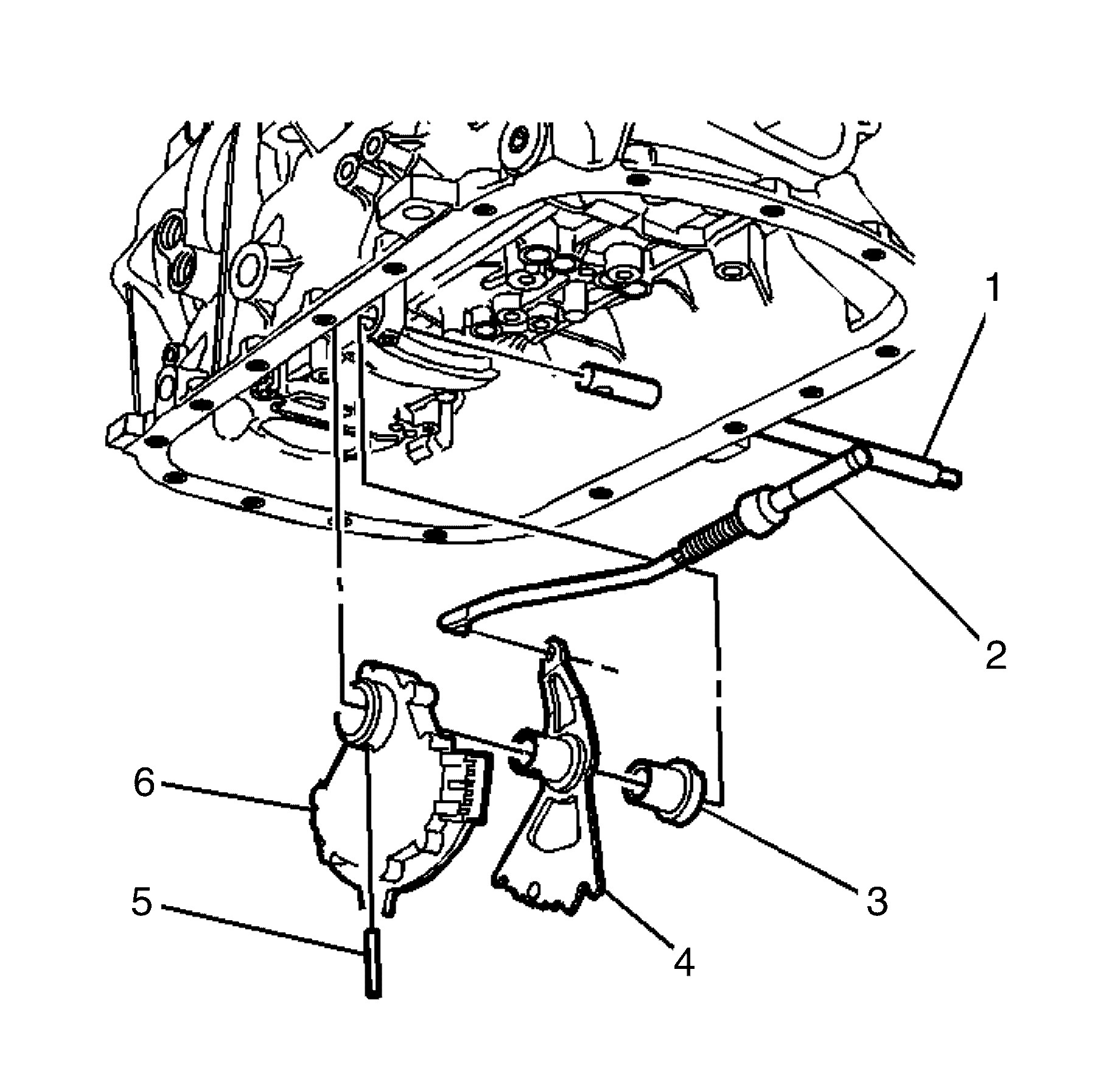
- Raise and support the vehicle. Refer to Lifting and Jacking the Vehicle.
- Remove the transmission manual shift shaft nut.
- Disconnect the shift linkage from the transmission manual shift shaft.
- Remove the exhaust system. Refer to Exhaust System Replacement.
- Remove the propeller shaft. Refer to Propeller Shaft Replacement.
- Support the powertrain with a suitable jack or table.
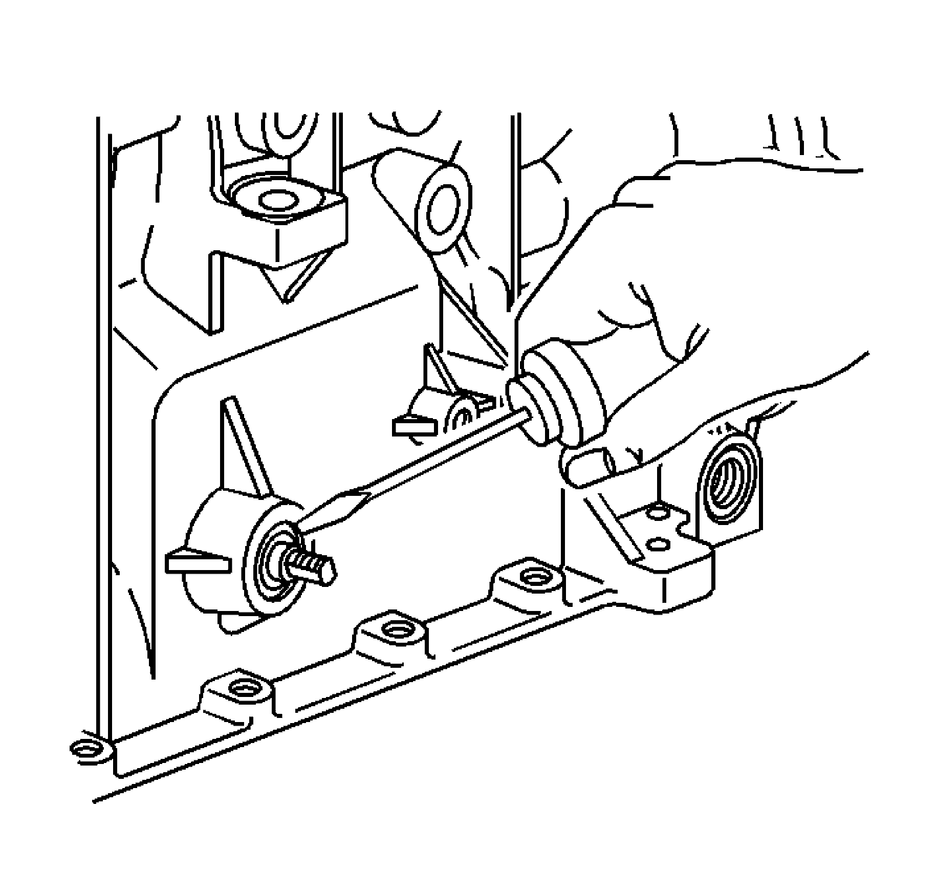
- Replace the front sub frame rear bolts and fit bolts from special tool kit, Refer to EN-48536 .
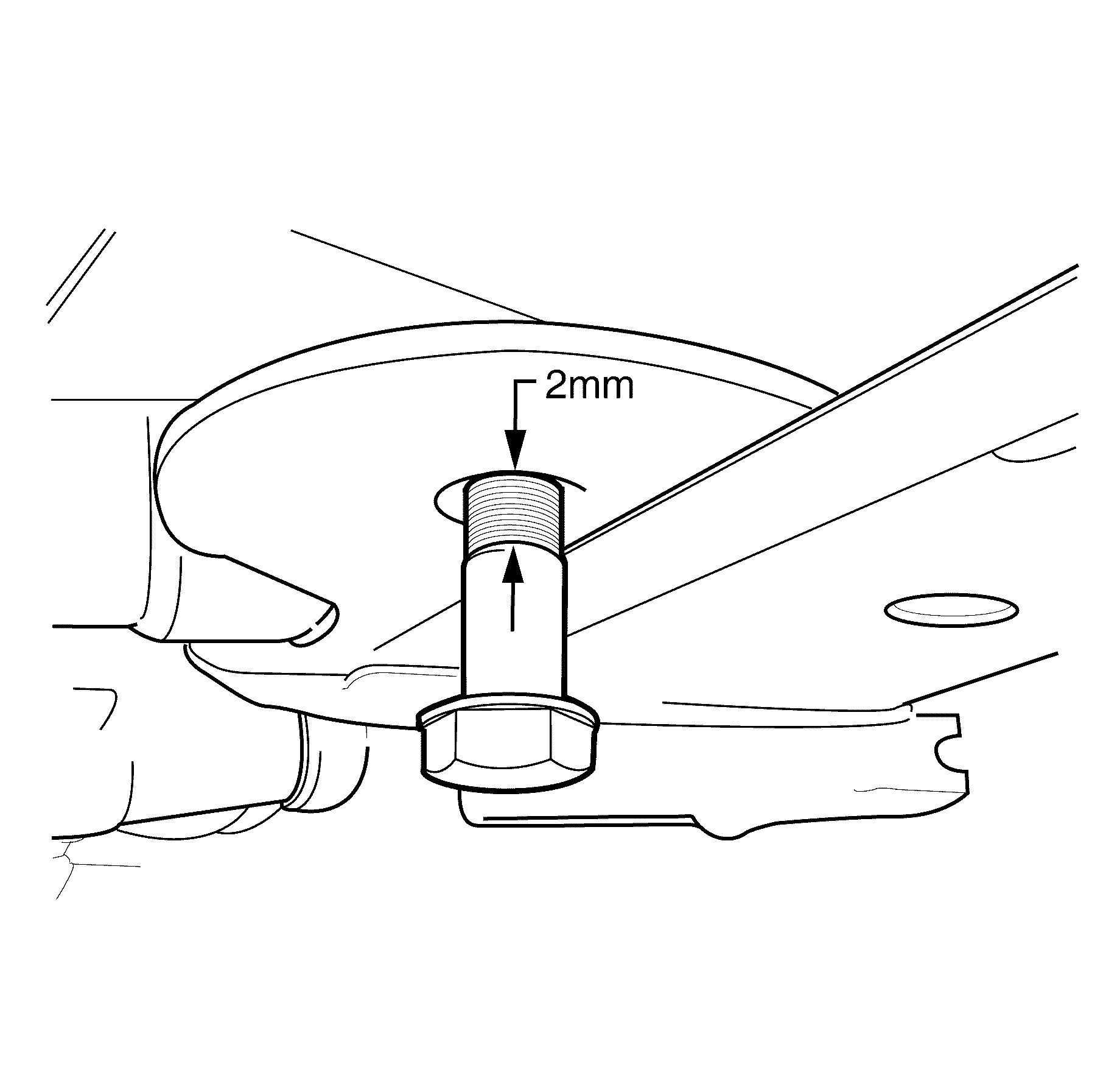
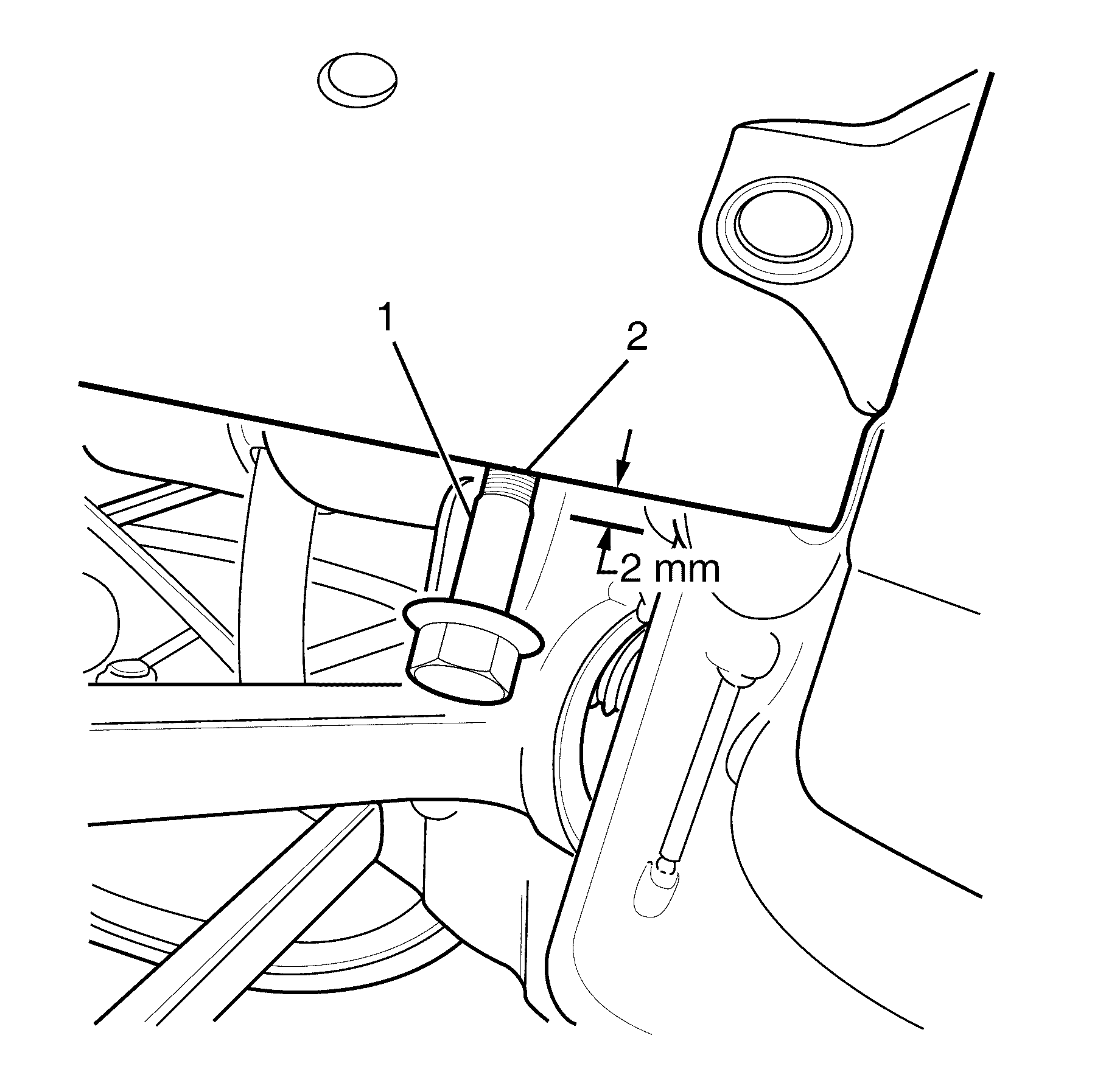
- Install bolt till stepped shank (1) is 2mm below sub frame (2).
- Replace the front sub frame front bolts and fit bolts from special tool kit , Refer to EN-48536 .
- Install bolt till stepped shank (1) is 2mm below chassis rail flange (2).
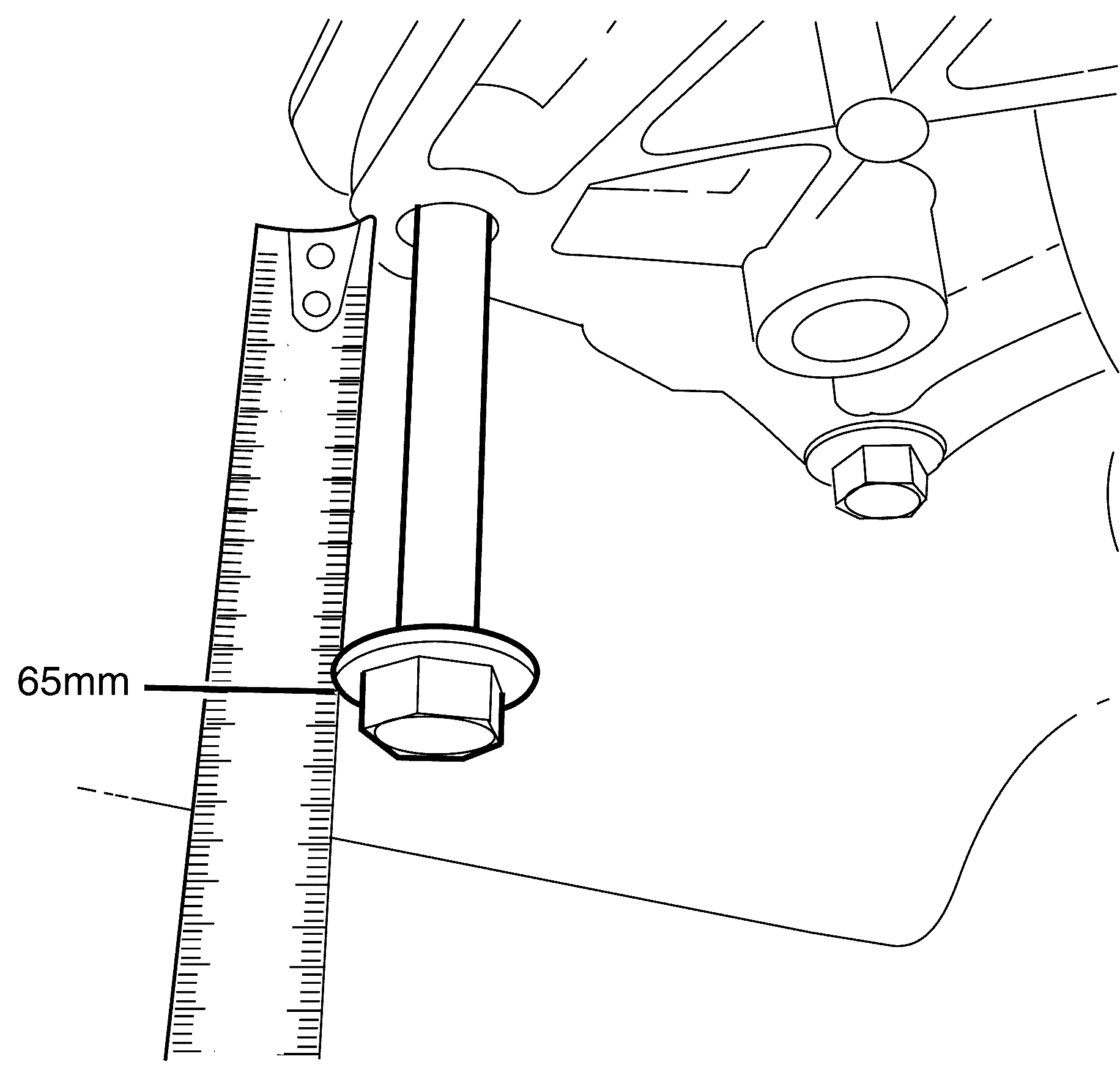
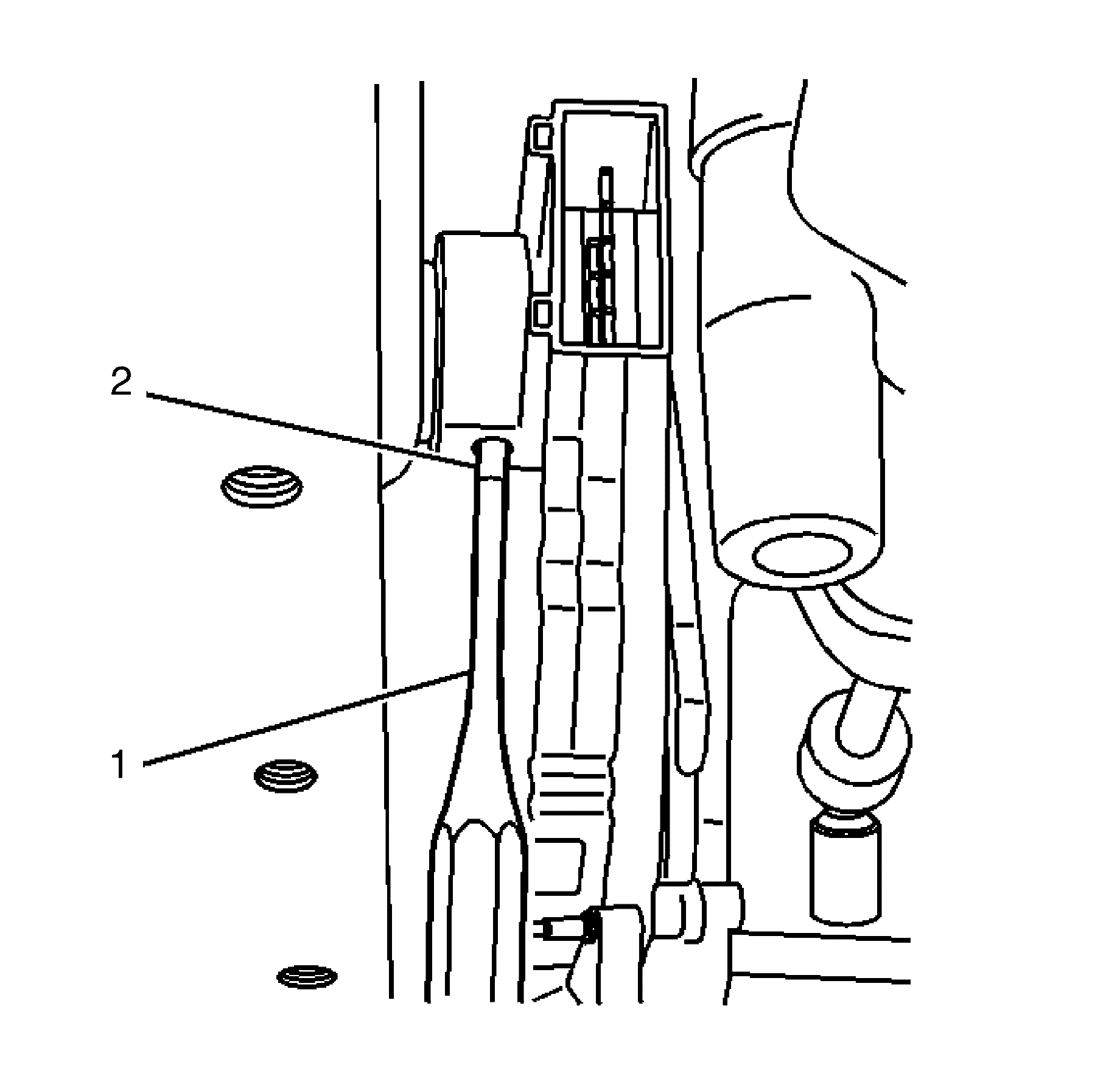
- Remove all four transmission mount to body bolt and install two bolts from special tool kit in diagonal holes e.g Left hand front and Right hand rear.
- Install in till 65mm is measured between bolt heads (1) and transmission mount (2).
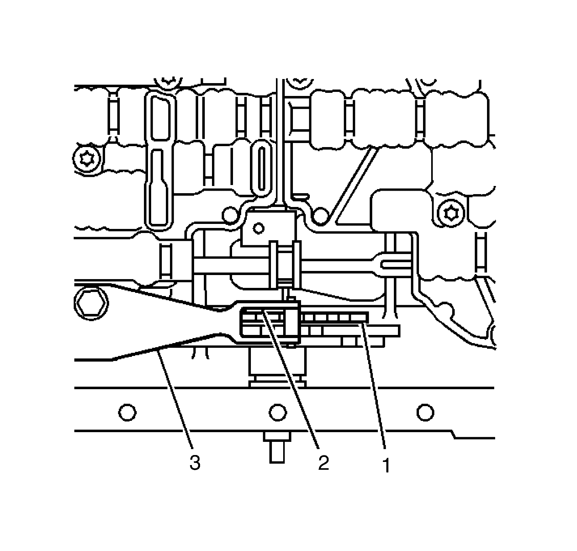
- Remove front sub frame middle bolts.
- Lower power train slowly untill the subframe and transmission mount are resting on bolts.
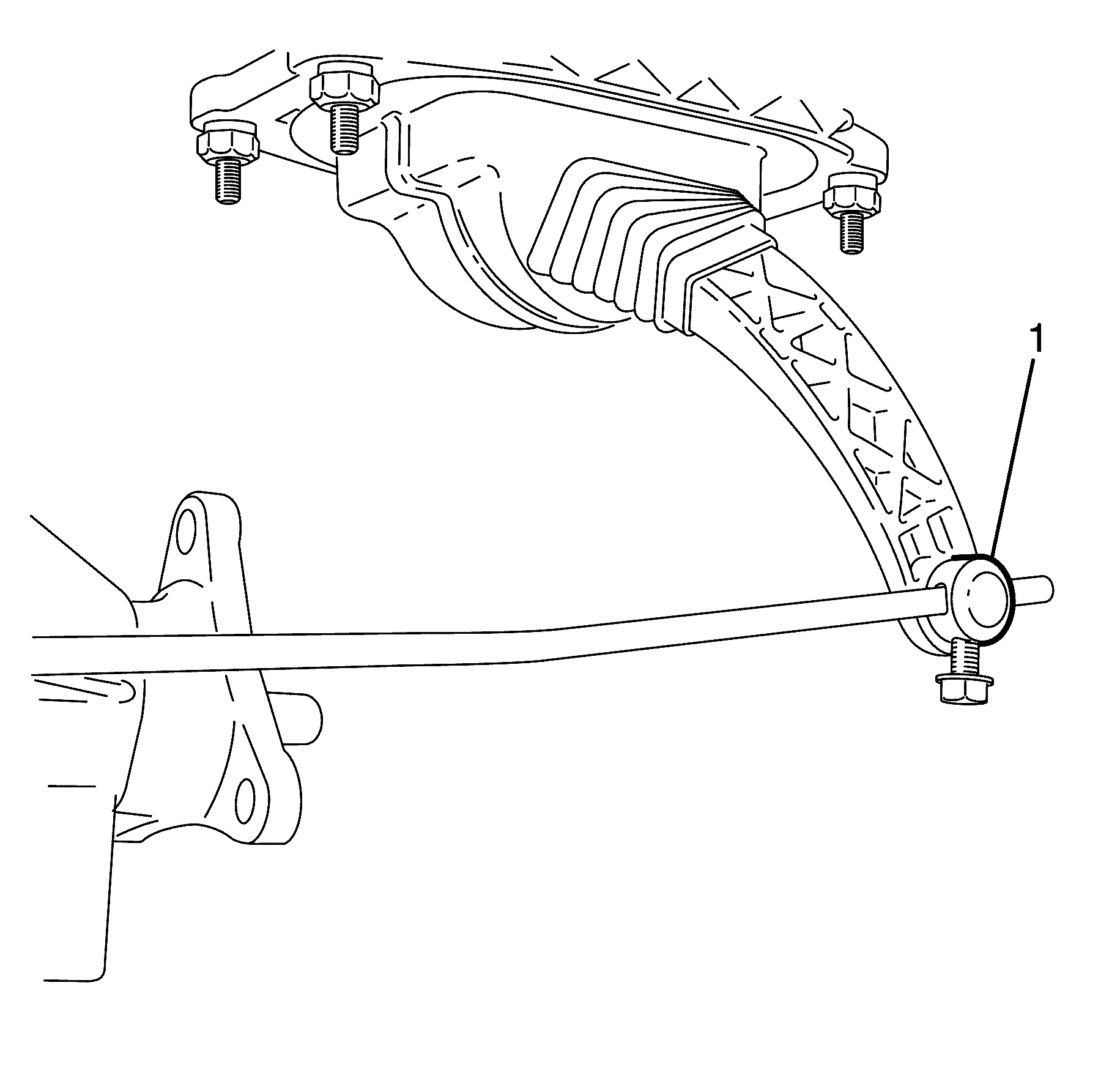
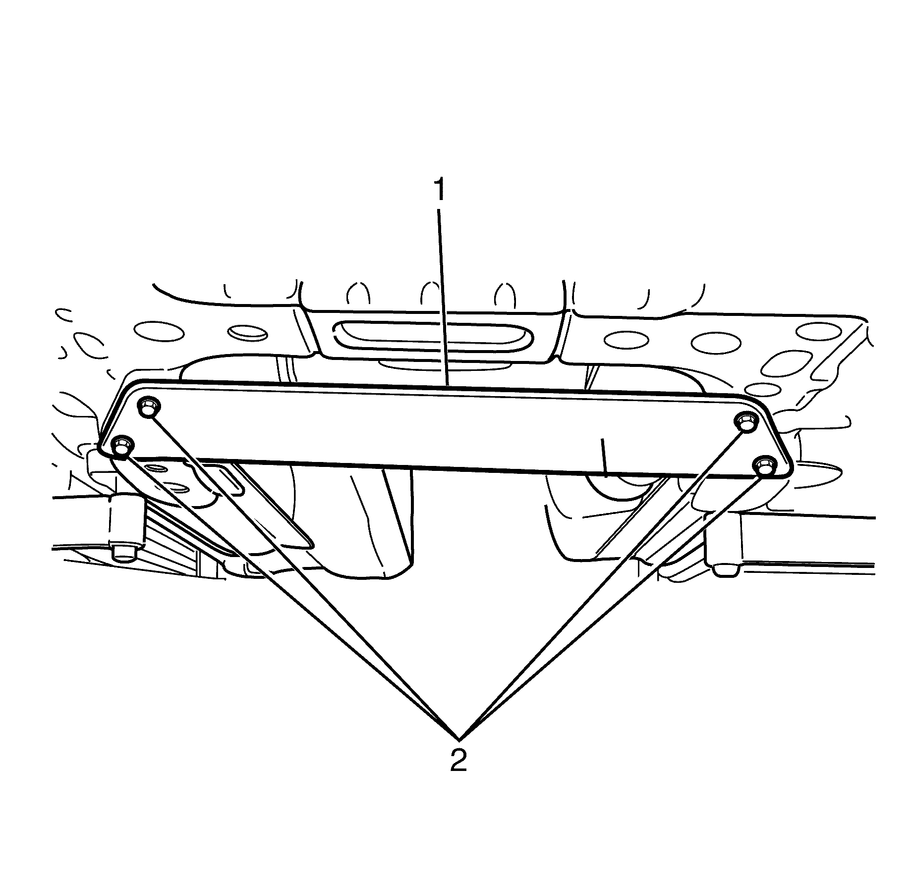
- Insert 65mm spacer blocks (1) between subframe (2) and chassis rails (3).
- Tighten the front sub frame front and rear bolts.
- Install and tighten the middle sub frame bolts.
- Remove supporting jack or table
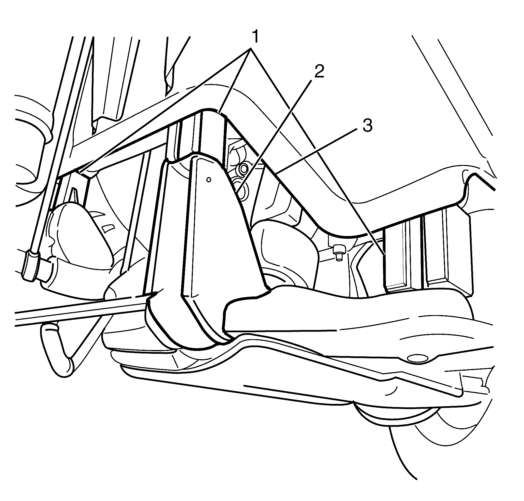
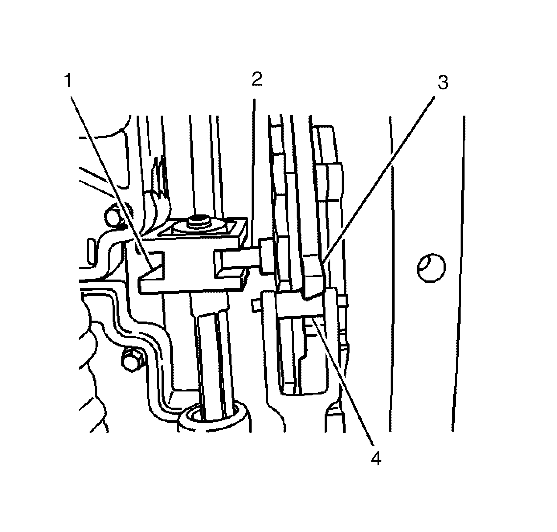
- Install engine support plate (1) to front sub frame (2).
- Tighten the plate securing bolts (3).
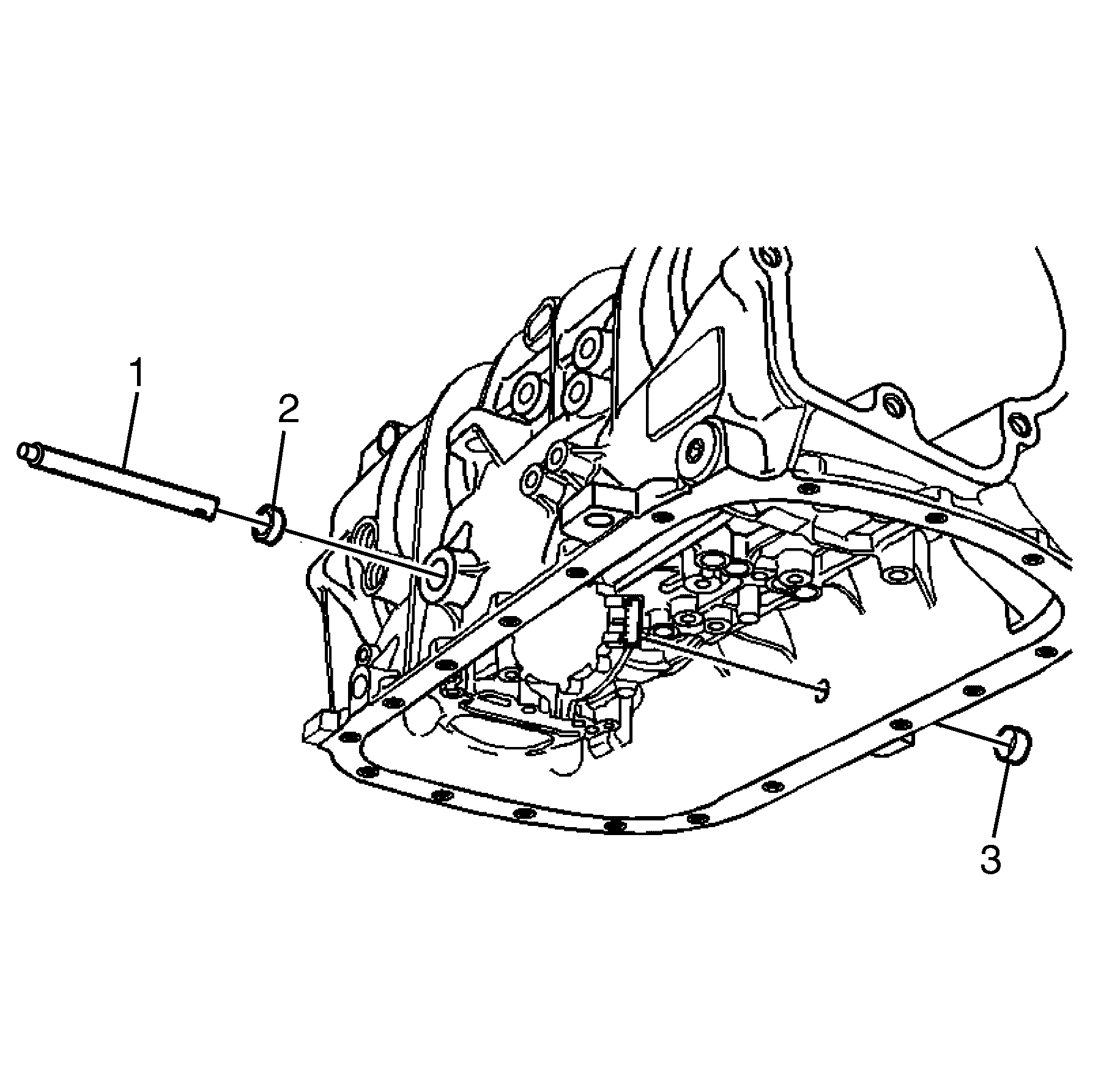
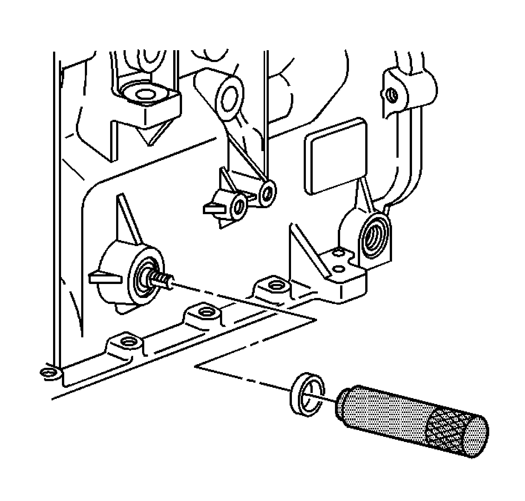
- Using a suitable tool, remove and discard the shaft seal.
- Using a suitable tool, remove and discard the cup plug.
- Remove the transmission fluid pan and filter. Refer to Automatic Transmission Fluid and Filter Replacement.
- Disconnect the selector lever electrical connector from the selector lever shaft position switch.
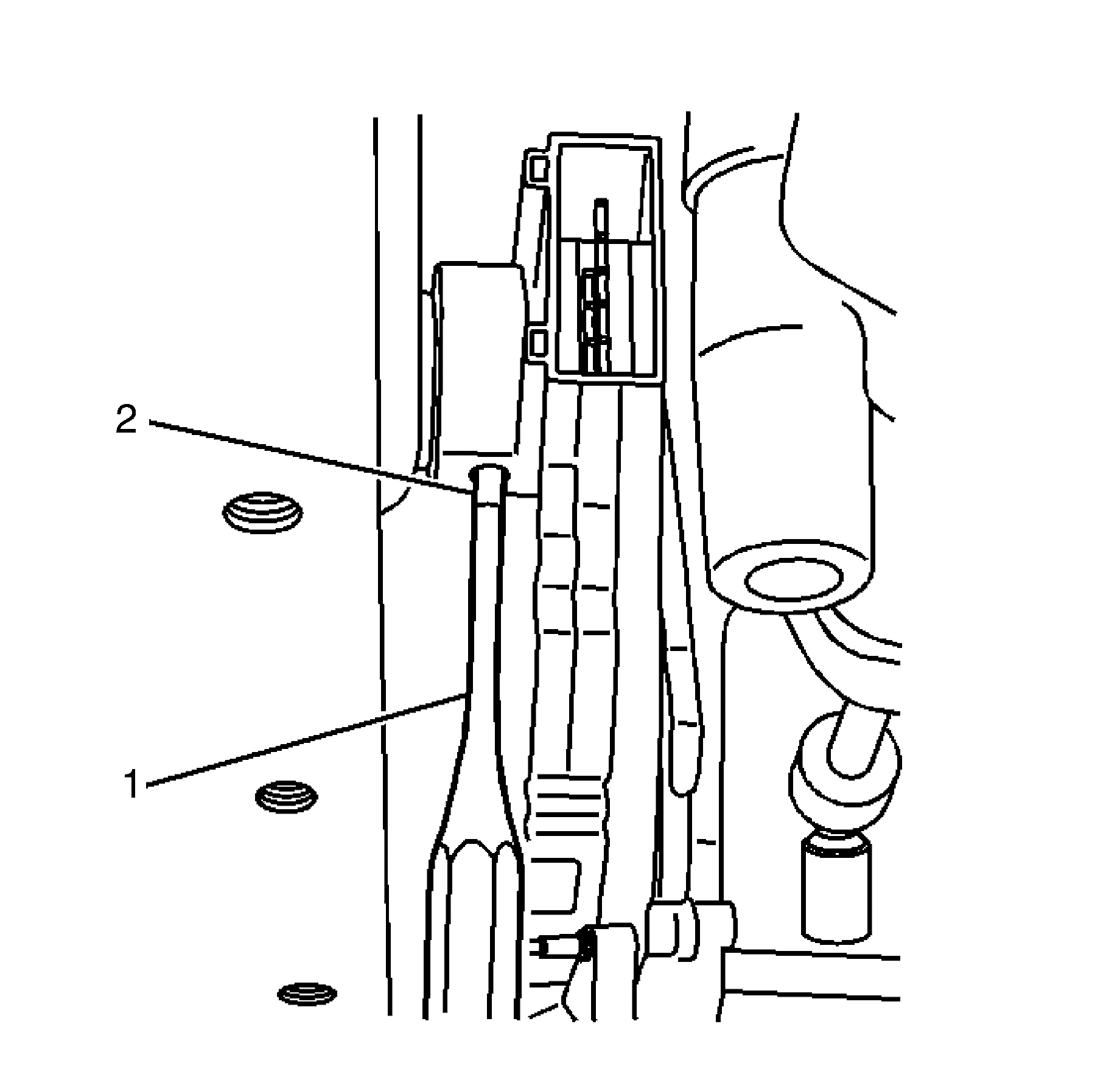
- Using a suitable pin punch (1). Remove the selector lever shaft position switch retaining pin (2).
- Remove the selector lever shaft detent spring (1) and retaining bolts (2).
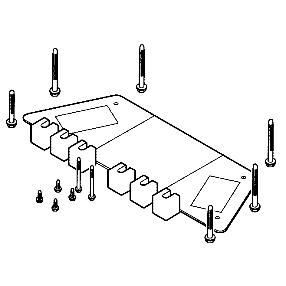
- Extract the manual shift shaft (1) from the transmission case only far enough to allow removal of the manual shift shaft position switch (6).
- Remove the manual shift shaft position switch (6), the manual shift shaft detent lever (4), the manual shift shaft assembly spacer (3), and the park pawl actuator (2) as an assembly.
Important: The engine mounts must NOT bend or deflect from the vertical position, damage to the mount will occur.
Tighten
Tighten the bolts to 95 N·m (70 lb. ft).
Tighten
Tighten the bolts to 95 N·m (70 lb. ft).
Tighten
Tighten the bolts to 10 N·m (89 lb. in).
Important: Replace the shaft seal if damaged or worn.
Important: Replace the cup plug if damaged or worn.
Important: Removal of the transmission is NOT required for the removal or replacement of the shift shaft position switch. Remove the transmission from the vehicle and refer to Unit Repair for replacement of the manual shift shaft ONLY if replacement of the manual shift shaft (3) is necessary.
Installation Procedure
- Install the manual shift shaft position switch (6), the manual shift shaft detent lever (4), the manual shift shaft assembly spacer (3), and the park pawl actuator (2) as an assembly. It may be necessary to push up on the park pawl in order to fully insert the park pawl actuator (2).
- Fully insert the manual shift shaft (1) into the transmission case.
- Install the manual shift shaft detent spring (1).
- Install the control valve body bolts (2) retaining the manual shift shaft detent spring. Do not tighten at this time.
- Confirm that the manual shift shaft detent lever locating pin (2) is properly engaged with the manual valve link (1).
- Confirm that the detent spring roller (4) is properly engaged with the manual shift shaft switch (3).
- Using a suitable pin punch (1). Install the manual shift shaft position switch retaining pin (2).
- Connect the electrical connector to the manual shift shaft position switch.
- Install a 0.8 mm spacer (2) between the manual shaft detent lever (1) and the manual shaft detent spring (3).
- tighten the detent spring bolts.
- Remove the spacer (2).
- Install the transmission fluid pan and filter. Refer to Automatic Transmission Fluid and Filter Replacement.
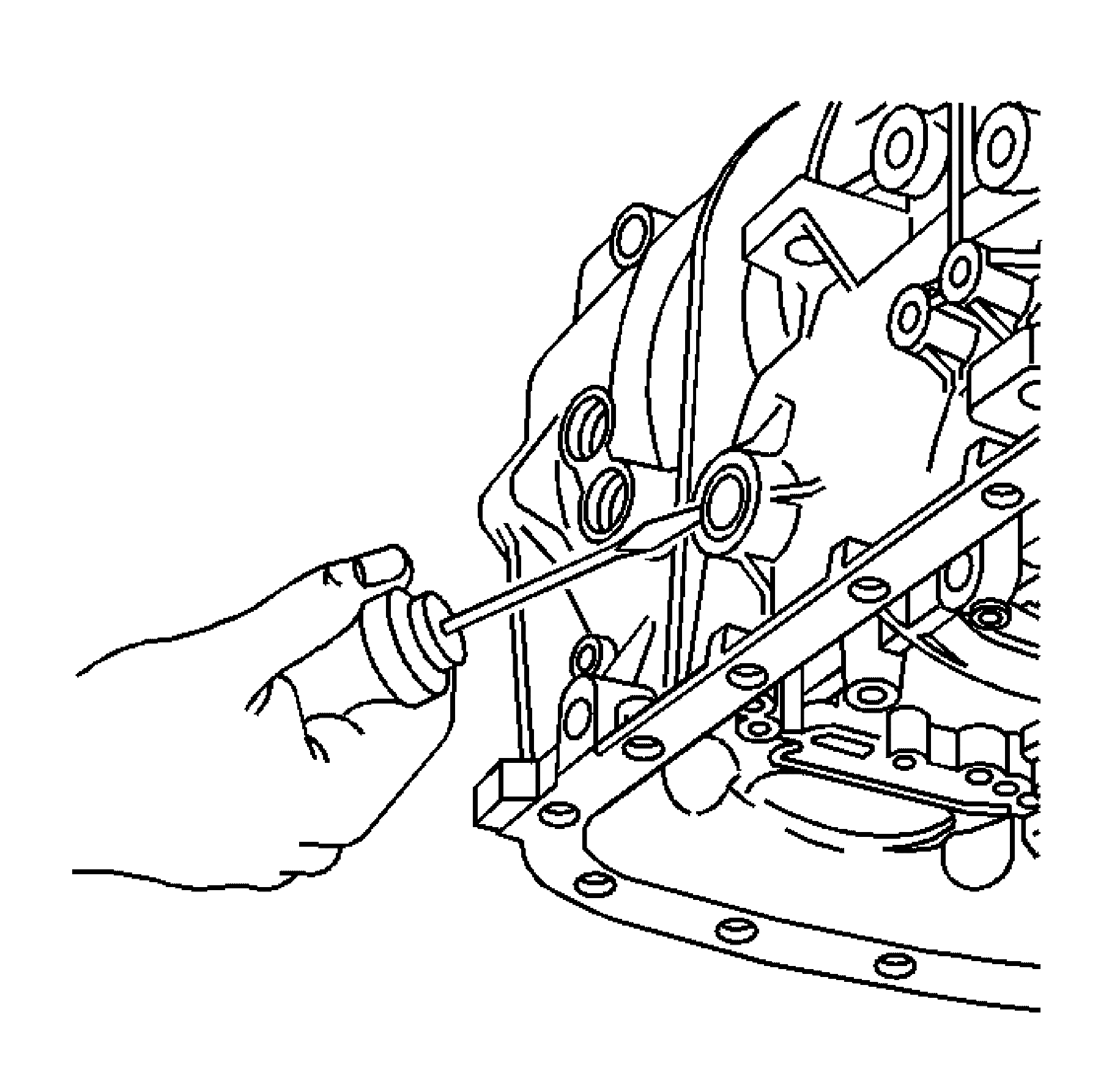
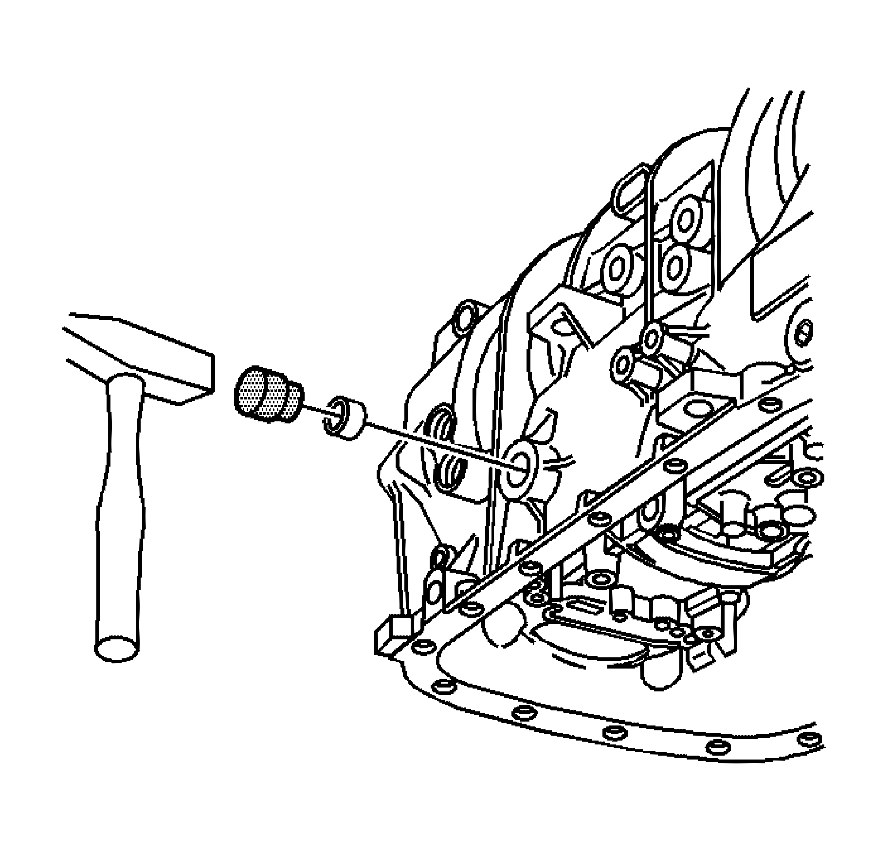
- If previously removed, install a new shaft seal using J 44767 .
- Position the seal onto the J 44767 before installing the seal into the transmission case.
- Carefully slide the seal and tool over the manual shift shaft and Insert the seal into the transmission until fully seated
- If previously removed, install a new cup plug. Lubricate the cup plug with transmission fluid before installation.
- Insert the cup plug into the transmission until flush with the transmission case.
- Remove engine and transmission lowering blocks and engine support plate.
- Raise the powertrain back up into the engine bay and support.
- Remove the special tool bolts and install the front sub frame bolts.
- Tighten the front sub frame bolts.
- Tighten the transmission support to under body retaining bolts.
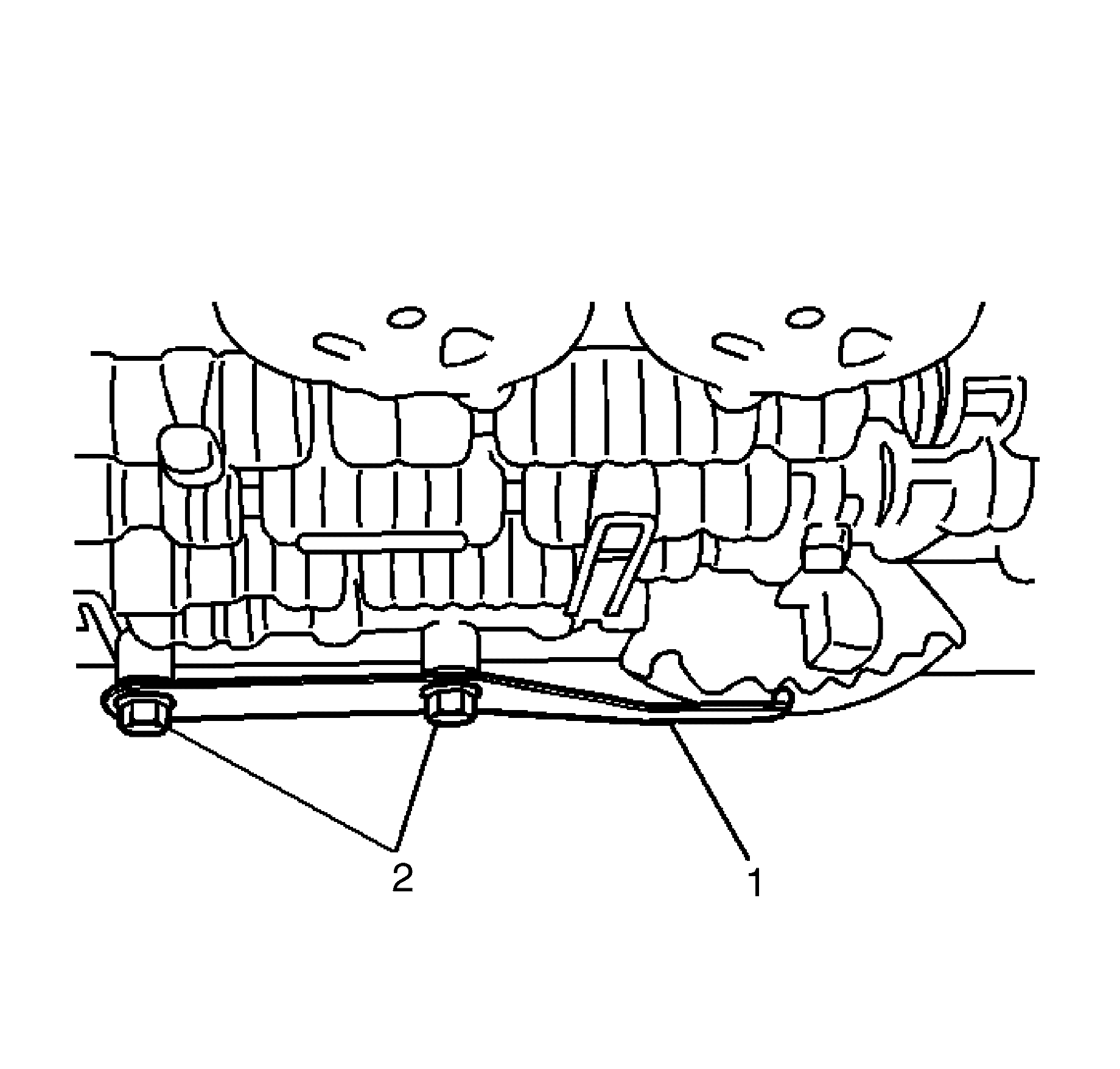
- Install the propeller shaft coupler (1) to the transmission flange. Refer to Propeller Shaft Replacement.
- Install the exhaust system. Refer to Exhaust System Replacement.
- Connect the shift linkage to the transmission manual shift shaft.
- Install the transmission manual shift shaft nut.
- Adjust the shift control linkage. Refer to Shift Control Linkage Adjustment.
- Lower the vehicle.
- Reset the TAP values. Refer to Transmission Adaptive Functions.
Notice: Refer to Fastener Notice in the Preface section.
Tighten
Tighten the bolts to 11 N·m (97 lb. in).
Tighten
Tighten the bolts to 160 N·m (118 lb. ft).
Tighten
Tighten the bolts to 63 N·m (46 lb. ft).
Tighten
Tighten the nut to 15 N·m (11 lb. ft).
Important: It is recommended that transmission adaptive pressure (TAP) information be reset.
Resetting the TAP values using a scan tool will erase all learned values in all cells. As a result, The ECM or TCM will need to relearn TAP values. Transmission performance may be affected as new TAP values are learned.