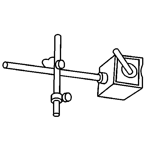
Tools Required
Caution: Refer to Safety Glasses Caution in the Preface section.
Caution: Refer to Vehicle Lifting Caution in the Preface section.
Caution: Refer to Brake Dust Caution in the Preface section.
Important:
| • | Brake disc assembled lateral runout (LRO) exceeding the maximum allowable
specification can cause thickness variation to develop in the brake disc over time,
usually between 10,000 [dash ] 20,000 km (6,200 [dash ] 12,400 mi). |
| • | Brake disc thickness variation MUST be inspected BEFORE inspecting for
assembled LRO. Thickness variation exceeding the maximum acceptable level can cause
brake pulsation. Refer to
Brake Rotor Thickness Variation Measurement
. |
- Matchmark the position of the brake disc to the wheel studs.
Important: Whenever the brake disc has been separated
from the hub/axle flange, any rust or contaminants should be cleaned from the hub/axle
flange and the brake disc mating surfaces. Failure to do this may result in too much
assembled LRO of the brake disc, which may lead to brake pulsation.
- Inspect the mating surface of the hub/axle flange and the brake disc to make
sure that there is no corrosion, foreign particles, rust, or debris. If the wheel
hub/axle flange and/or brake disc mating surfaces exhibit these conditions, perform
the following steps:
| 2.2. | Clean any rust or corrosion from the mating surface of the hub/axle flange. |
| 2.3. | Clean any rust or corrosion from the mating surface of the brake disc. |
| 2.4. | Clean the friction surfaces of the brake disc with denatured alcohol,
or an equivalent approved brake cleaner. |
- Install the disc to the hub/axle flange using the matchmark made prior
to removal.
Important: Install the wheel nuts in reverse avoid damage
to the tapers.
- Install 2 wheel nuts in reverse to opposite wheel studs to retain the brake
disc to the hub.
- Mount a dial indicator and position the indicator button so it contacts
the brake disc friction surface at a 90 degree angle, approximately 10 mm
(3/8 in) from the outer edge of the brake disc.
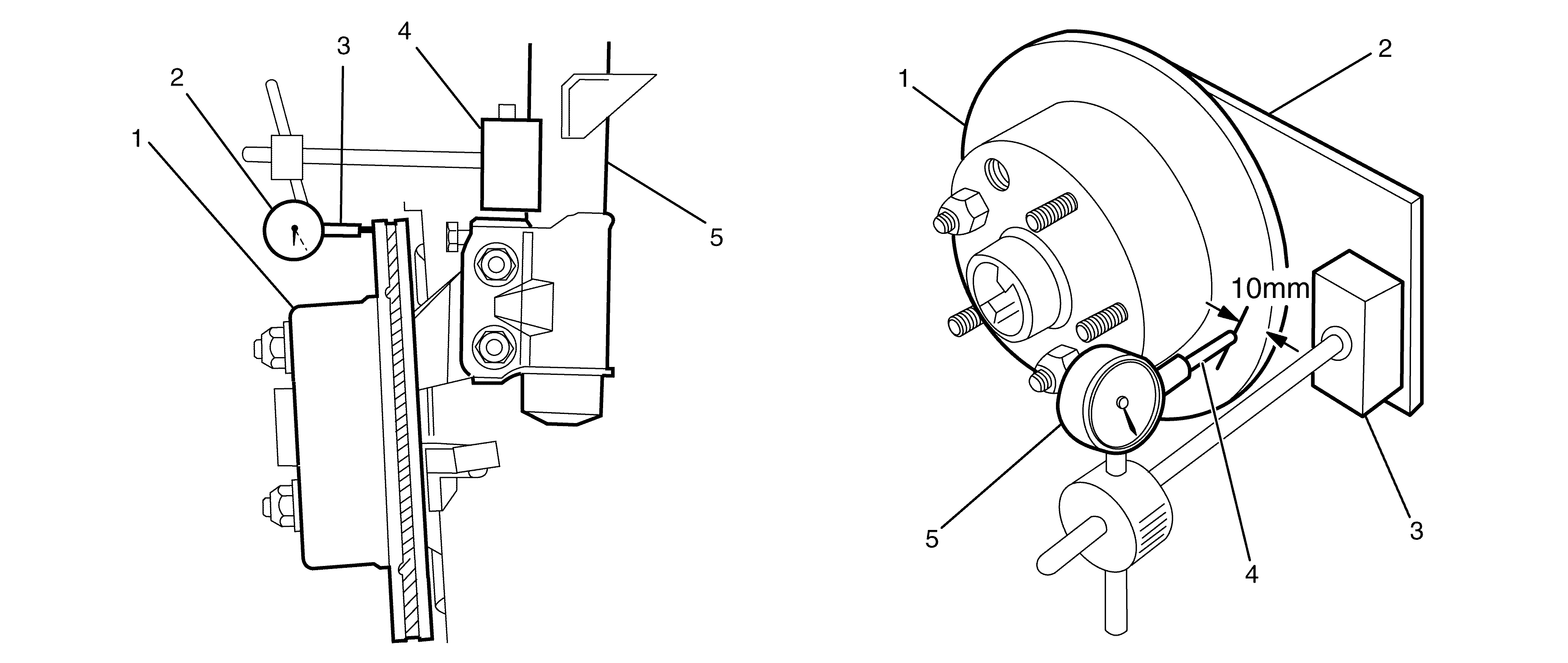
| | Important: The dial indicator's magnetic mounting base (4)
must be securely mounted to the front strut unit (5).
|
| • | To measure the front brake disc assembled LRO (View A), set up a dial
indicator (2) on a magnetic mounting base (4) and attach to the front
strut unit (5) above the brake disc (1). |
| | Important: The dial indicator's magnetic mounting base (3)
must be securely mounted to the dial indicator plate (2).
|
| • | To measure the rear brake disc assembled LRO (View B), bolt the dial
indicator plate (2) to the brake caliper attaching points on the rear knuckle.
Set up a dial indicator (4) on a magnetic mounting base (3) and attach
to the dial indicator plate (2). Refer to Dial Indicator Plate in Special Tools
for dial indicator plate details. |
- Measure and record the assembled LRO of the brake disc:
| 6.1. | Rotate the brake disc until the lowest reading is displayed on the indicator
dial, then set the dial to zero. |
| 6.2. | Rotate the brake disc until the highest reading is displayed on the dial. |
| 6.3. | Mark the location of the high spot relative to the nearest wheel stud,
or studs. |
| 6.4. | Measure and record the amount of assembled LRO. |
- Compare the brake disc assembled LRO to the following specification:
Specification
| • | Front brake disc maximum allowable assembled lateral runout: 0.05 mm
(0.002 in). |
| • | Rear brake disc maximum allowable assembled lateral runout: 0.05 mm
(0.002 in). |
- If the brake disc assembled LRO measurement exceeds the specification,
refer to
Brake Rotor Assembled Lateral Runout Correction
.
- If the brake disc assembled LRO measurement is within specification, install
the brake caliper and depress the brake pedal several times to secure the brake disc
in place before removing the wheel nuts.
