Tools Required
KM-507-C Ball Joint Remover
Removal Procedure
- Disconnect the negative battery cable.
- Raise and support the vehicle. Refer to Lifting and Jacking the Vehicle .
- Remove the front tire and wheel assemblies. Refer to Tire and Wheel Removal and Installation .
- Place a drain pan under the steering gear to catch the power steering fluid.
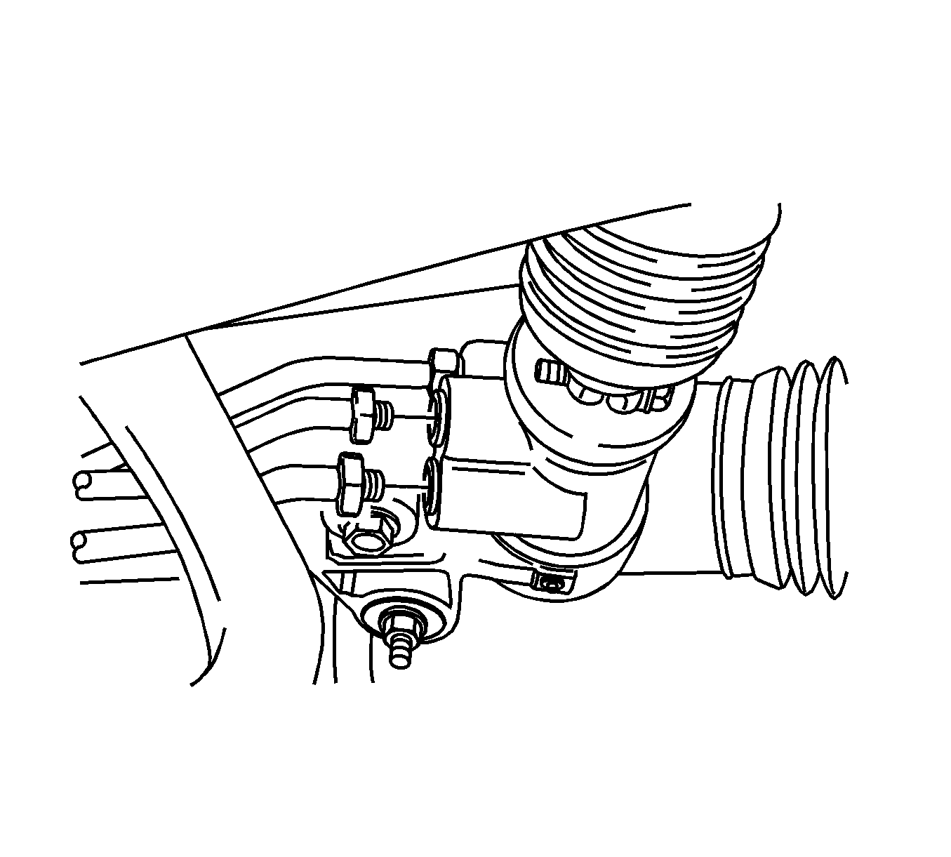
- Disconnect the power steering gear fluid outlet pipe.
- Disconnect the power steering gear fluid inlet pipe.
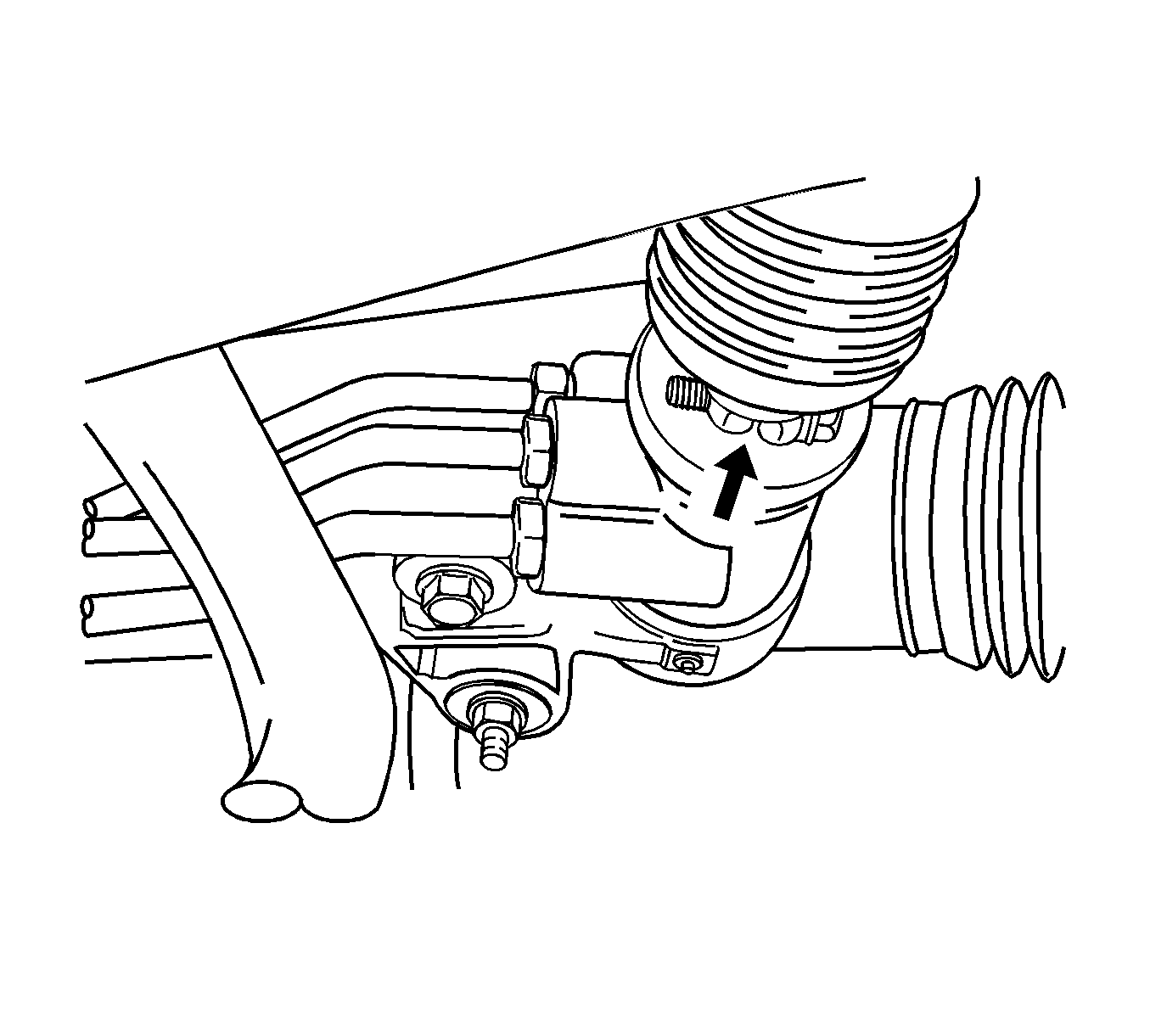
- Position the steering gear straight ahead by turning the steering wheel.
- Scribe a mark on the stub shaft housing that lines up with a mark on the intermediate shaft lower coupling.
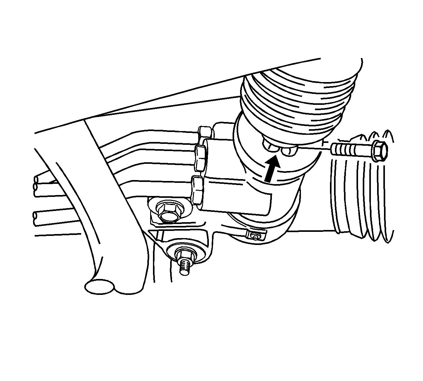
- Remove the intermediate shaft pinch bolt.
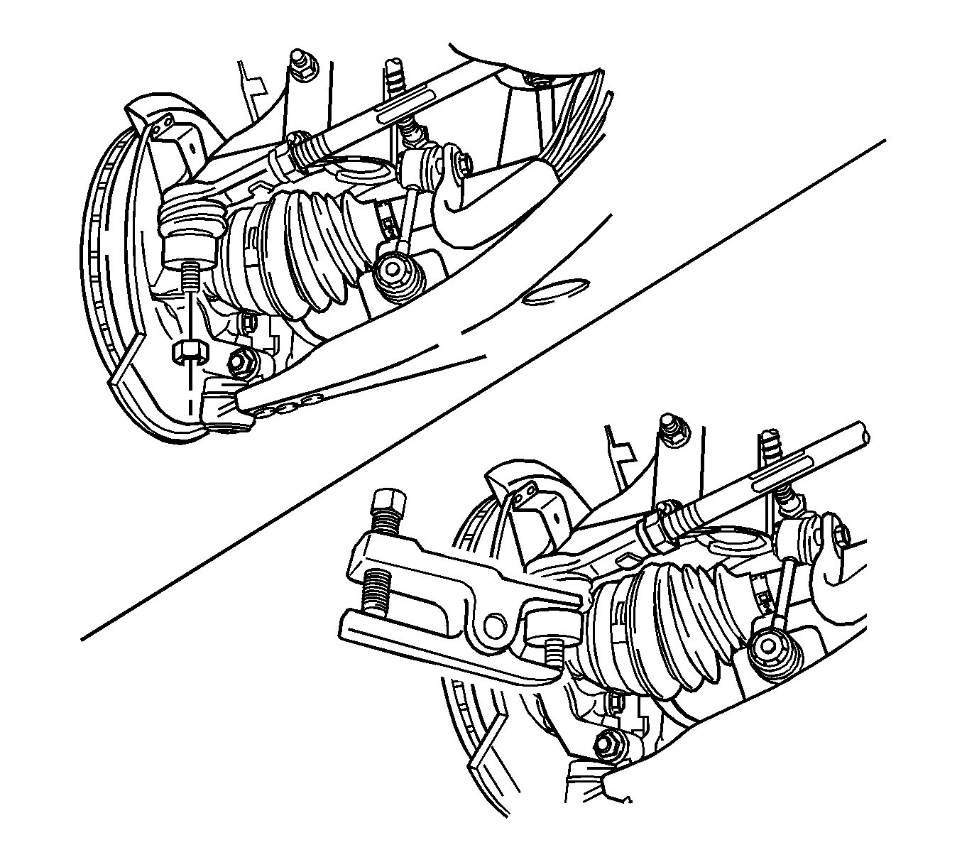
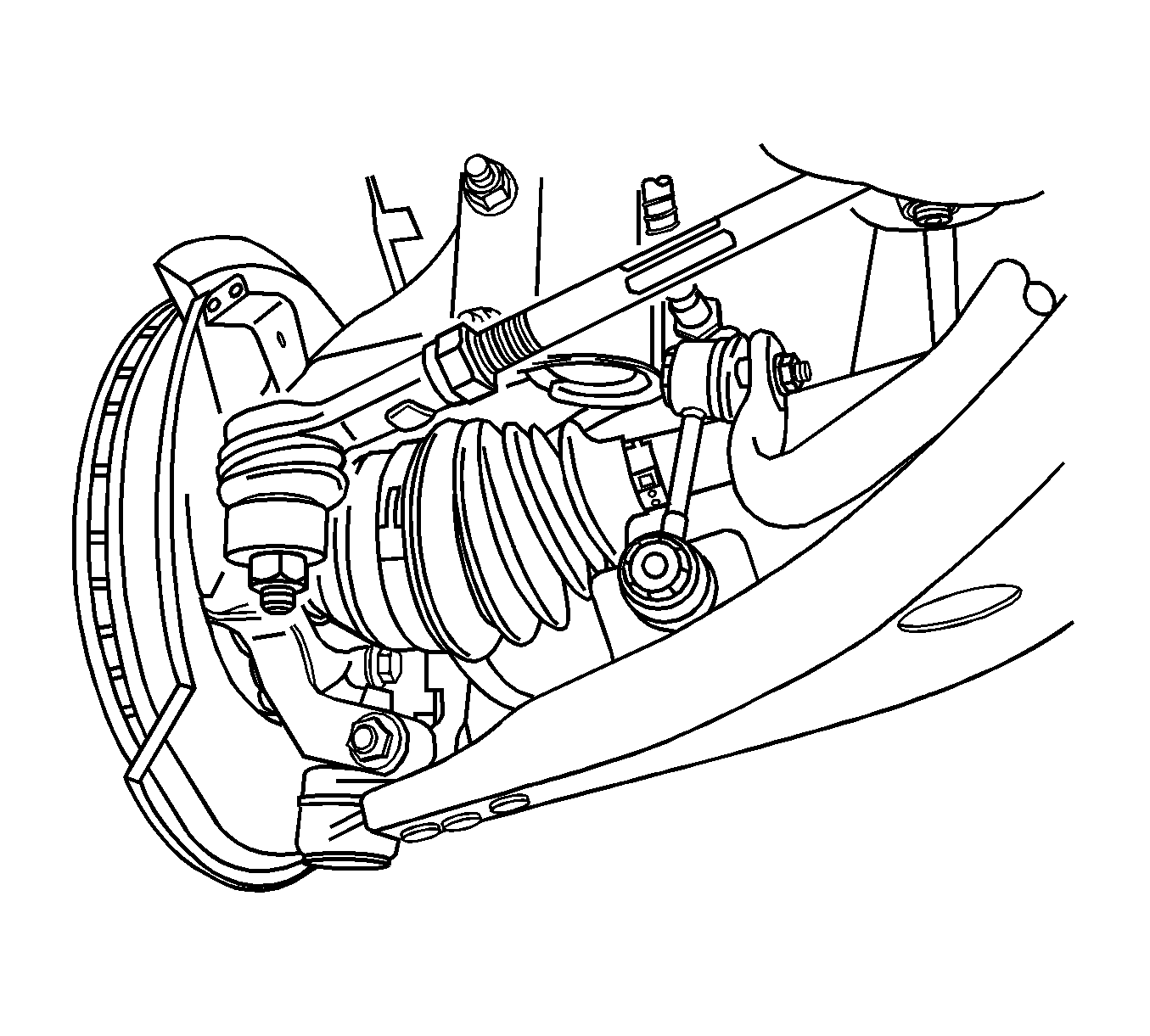
- Remove the outer tie rod nuts and disconnect the tie rod ends from the strut assembly using the KM-507-C .
- Remove the front crossmember assembly. Refer to Front Suspension Crossmember Replacement .
- Remove the transaxle center bracket, if equipped with automatic transaxle. Refer to Transmission Mount Bracket Replacement .
- Remove the bolts securing the transaxle center bracket to the transaxle and the engine, if equipped with a manual transaxle. Move the transaxle center bracket out of the way.
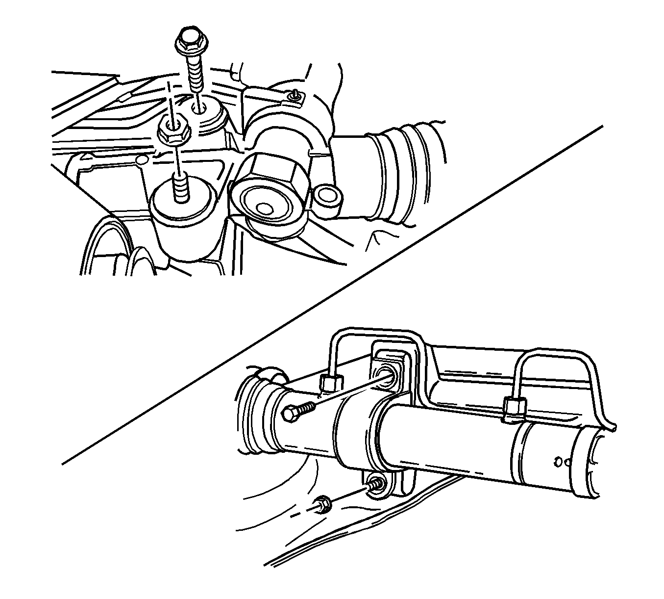
- Remove the nuts and bolts from the steering gear mounting bracket.
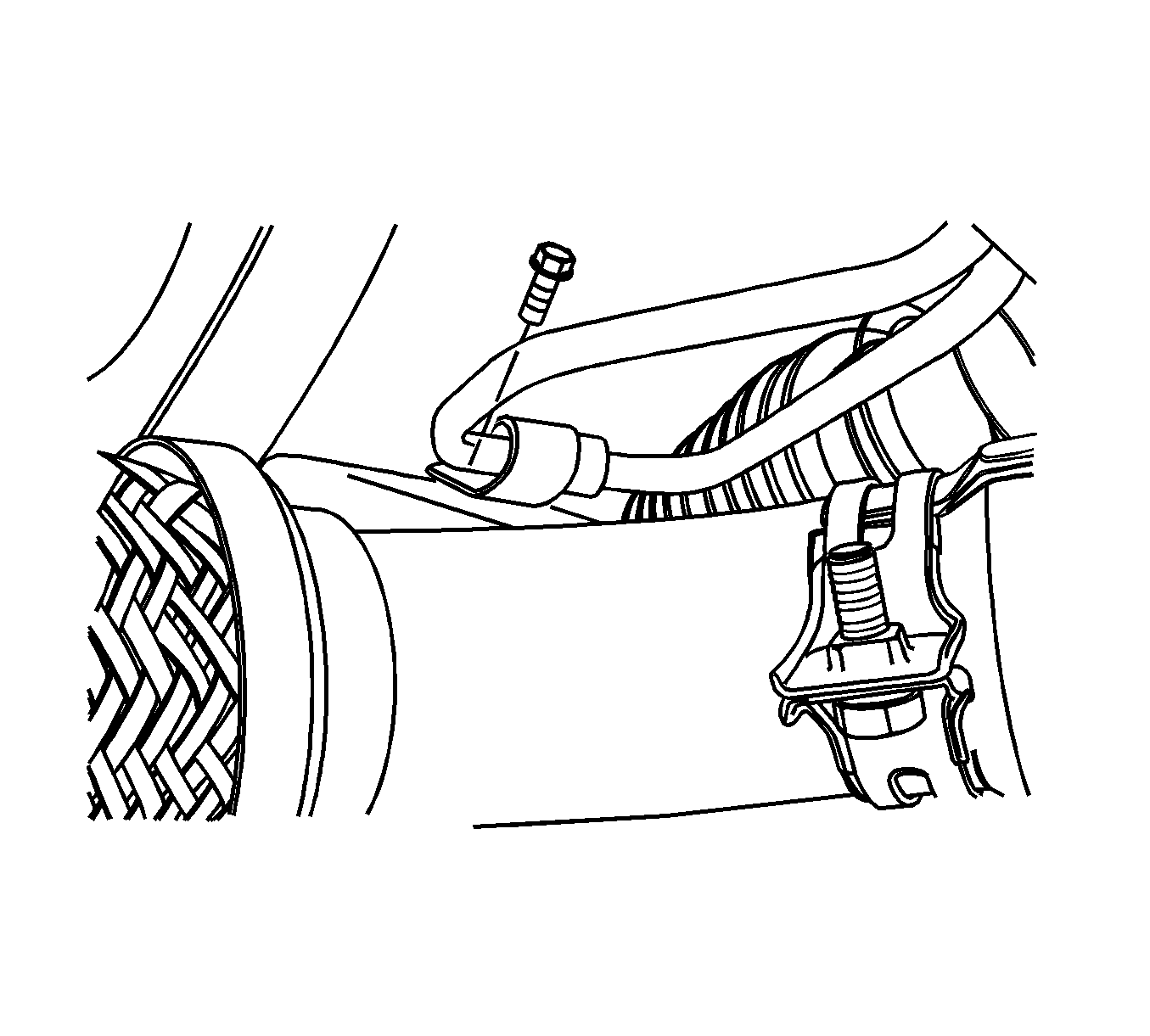
- Remove the return line from the clip on the crossmember.
- Disconnect the rack and pinion assembly from the crossmember assembly.
Caution: Refer to Battery Disconnect Caution in the Preface section.
Installation Procedure
- Install the rack and pinion assembly on the crossmember. Align the marks on the shafts to ensure proper positioning. Seat the stub shaft into the intermediate shaft.
- Install the bolts and nuts on the steering gear mounting bracket.
- Install the return line into the clip on the crossmember.
- Position the transaxle center bracket in place and install the bolts securing the bracket to the engine and the transaxle, if equipped with manual transaxle.
- Install the transaxle center bracket, if equipped with an automatic transaxle. Refer to Transmission Mount Bracket Replacement .
- Install the front crossmember. Refer to Front Suspension Crossmember Replacement .
- Connect the tie rod ends to the strut assembly.
- Install the outer tie rod nuts.
- Install the lower intermediate shaft pinch bolt.
- Connect the power steering gear fluid inlet and outlet pipe.
- Install the wheels. Refer to Tire and Wheel Removal and Installation .
- Lower the vehicle.
- Perform a front toe adjustment. Refer to Front Toe Adjustment .
- Do a straight-ahead check. Refer to Straight Ahead Inspection .
- Refill the power steering system and check for leaks. If leaks are found, correct the cause of the leak and bleed the system. Refer to Power Steering System Bleeding .
- Connect the negative battery cable.

Important: The steering gear and the steering wheel must be in the straight-ahead position.
Notice: Refer to Fastener Notice in the Preface section.

Tighten
Tighten the steering gear mounting bracket bolts and nuts to 60 N·m (44 lb ft).

Tighten
Tighten the return line clip bolt to 8 N·m (71 lb in).
Tighten
Tighten the transaxle center bracket-to-transaxle bolts and the transaxle center bracket-to-engine bolt to 80 N·m (59 lb ft).
Tighten
Tighten the outer tie rod nuts to 50 N·m (37 lb ft).

Tighten
Tighten the lower intermediate shaft pinch bolt to 25 N·m (18 lb ft).

Tighten
Tighten the steering gear inlet and outlet pipe fitting to 28 N·m (21 lb ft).
Notice: Refer to Using Proper Power Steering Fluid Notice in the Preface section.
