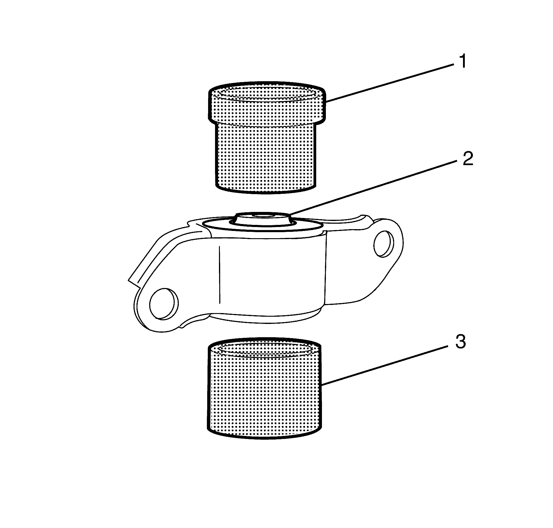
Tools Required
KM-619 Bushing Remover/Installer.
Removal Procedure
- Raise and support the vehicle. Refer to Lifting and Jacking the Vehicle.
- Remove the rear frame. Refer to Rear Frame Replacement.
- Remove the upper control arm pivot bushing to upper control arm retaining bolt (4).
- Remove the upper control arm pivot bushing bracket to subframe retaining bolts (1).
- Remove the upper control arm pivot bushing (2) and bracket (3) assembly from the upper control arm (5).
- Remove the upper control arm pivot bushing (2) using the KM-619 (1, 3).
- Inspect all parts for wear and damage.
Caution: Refer to Safety Glasses Caution in the Preface section.
Caution: Refer to Vehicle Lifting Caution in the Preface section.
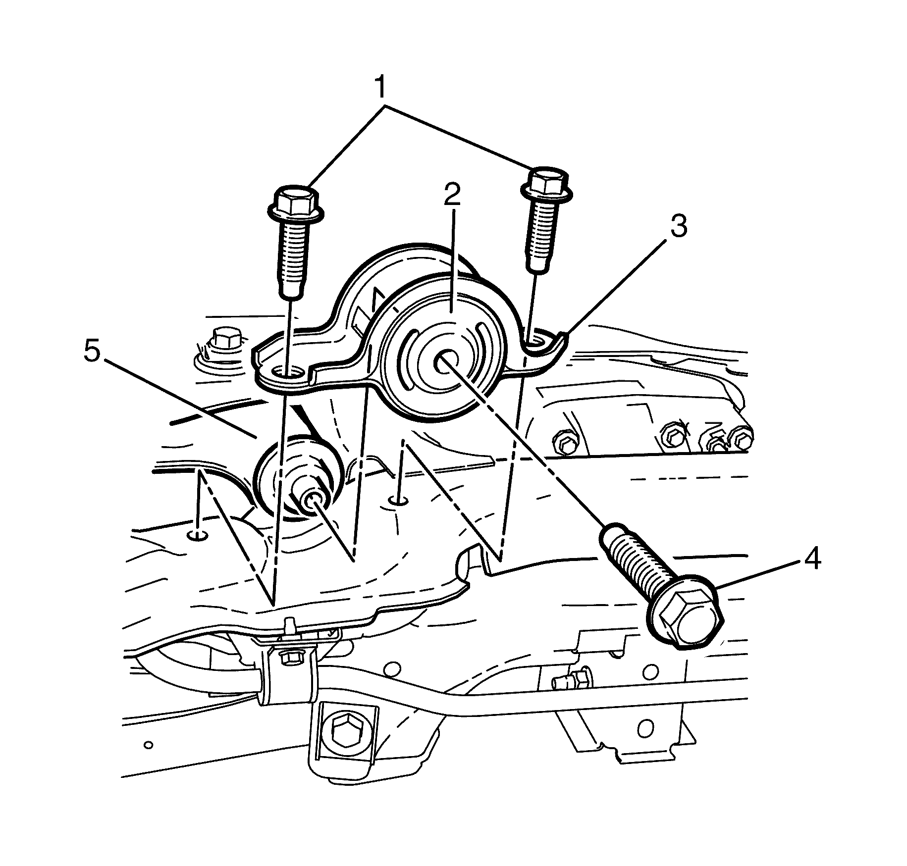
Important: Mark the location of the pivot bushing bracket relative to the rear frame for correct re-assembly.
Important: If both upper control arm pivot bushings are to be replaced at the same time, the upper control arm pivot bushing brackets must be marked as left or right. In all cases, the upper control arm pivot bushing bracket must be marked with an arrow facing towards the front of the vehicle.
Important: The orientation of the asymmetrical bush is critical to its function. Observe the orientation and depth of the upper control arm pivot bushing (2) with reference to the original position. Adhering to this recommendation will minimize the poential of incorrect upper control arm pivot bushing (2) installation.
Important: The upper control arm pivot bushing (2) must be lubricated with soapy water solution to ease the removal process.
Installation Procedure
- Install the upper control arm pivot bushing (2) to the upper control arm (3) using the KM-619 (1, 3).
- Install the upper control arm pivot bushing (2) and bracket (3) assembly to the upper control arm (5).
- Install the upper control arm pivot bushing bracket to subframe retaining bolts (1).
- Install the upper control arm pivot bushing to upper control arm retaining bolt (4).
- Install the rear frame. Refer to Rear Frame Replacement.
- Remove the safety stands.
- Lower the vehicle to the ground.
- Check the vehicle rear wheel alignment and adjust if necessary. Refer to Wheel Alignment Specifications.
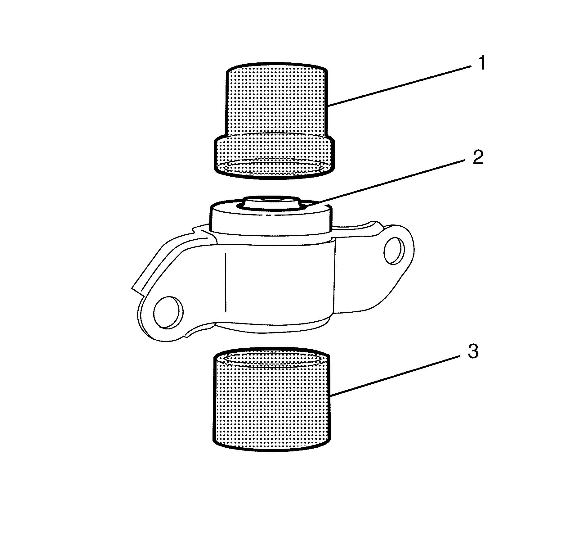
Important: The upper control arm pivot bushing (2) must be lubricated with soapy water solution to ease the installation process.
Important: Before installing, the upper control arm pivot bushing (2) must be correctly aligned and orientated. The depth to which the upper control arm pivot bushing (2) is going to travel must also be observed and maintained.
Important: Align the pivot bushing bracket to the mark made prior to removal.
Important: The upper control arm pivot bushing bracket directional marks must be observed before installation.
Notice: Refer to Fastener Notice in the Preface section.
Tighten
Tighten the bolts a first pass to 40 N·m
(29 lb ft).
Tighten the bolts a final pass 90 Degrees.
Tighten
Tighten the bolt to 170 N·m (125 lb ft).
