Adjust Link Replacement LWB SWB
Removal Procedure
- Raise and support the vehicle. Refer to Lifting and Jacking the Vehicle.
- Remove the rear wheel. Refer to Tire and Wheel Removal and Installation.
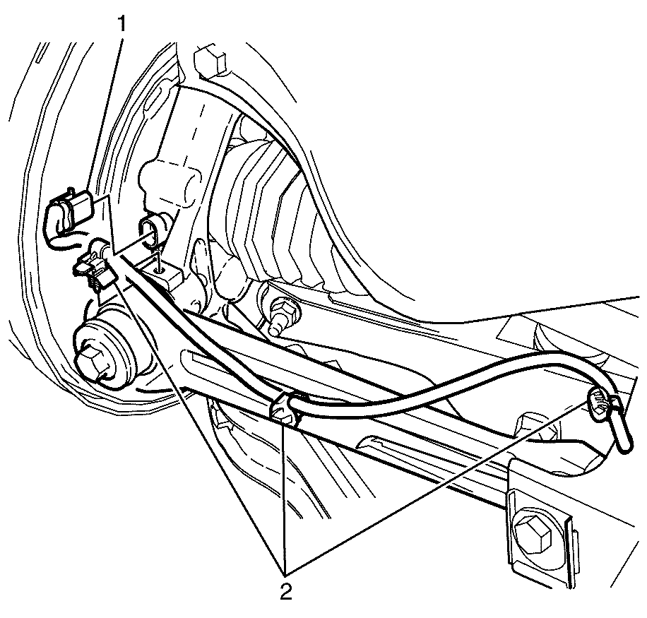
- Disconnect the wheel speed sensor electrical connector (1).
- Detach the wheel speed sensor wiring harness retainers (2).
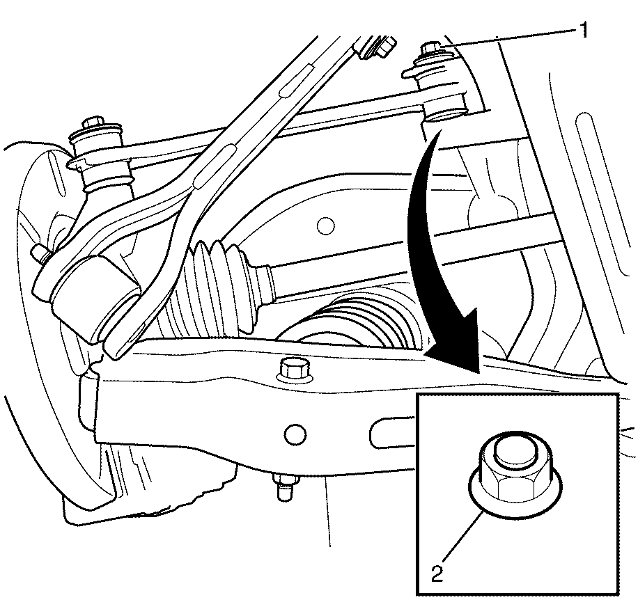
- Remove the I-Link to subframe retaining nut (1), eccentric washer (2) and retaining bolt (3).
- Discard the I-Link to subframe retaining nut (1).
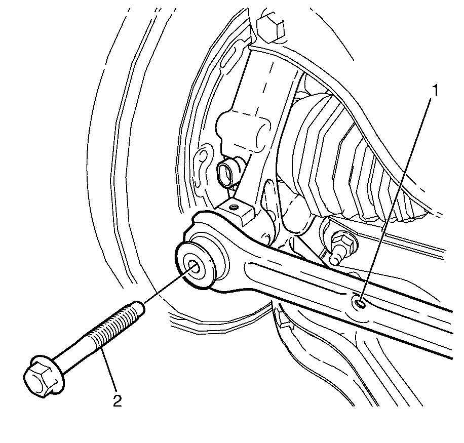
- Remove the I-Link to knuckle retaining bolt (2).
- Remove the I-Link from the subframe (1).
Caution: Refer to Safety Glasses Caution in the Preface section.
Caution: Refer to Vehicle Lifting Caution in the Preface section.
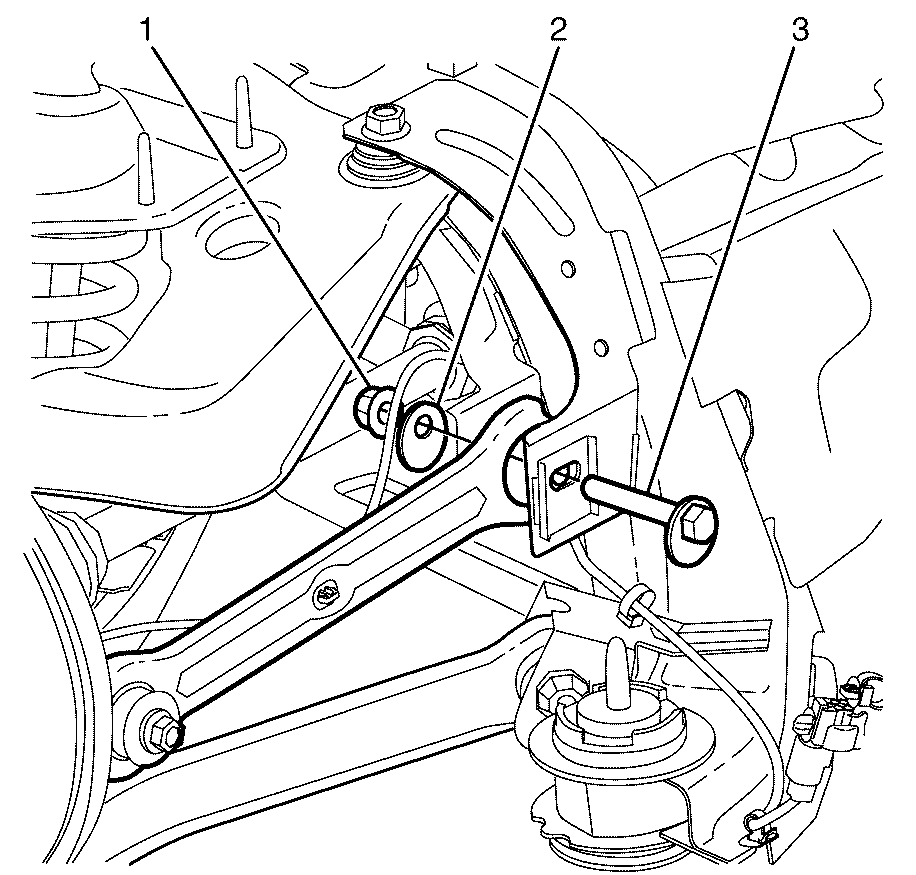
Important: Mark the I-Link to subframe retaining bolt (3) in relation to the subframe before removing the I-Link to subframe retaining nut (1).
Installation Procedure
- Install the NEW I-Link (1)
- Install the I-Link to knuckle retaining bolt (2).
- Loosen the bolt by 90 degrees
- Install the I-Link to subframe retaining bolt (3), washer (2) and NEW nut (1).
- Using a suitable tool, align the previously made aligning mark on the I-Link to subframe retaining bolt (3) to the corresponding rear subframe mark.
- Using a suitable tool, hold the I-Link to subframe retaining bolt (3) in the correct position and tighten the NEW nut (1).
- Loosen the nut by 90 degrees.
- Install the rear wheel. Refer to Tire and Wheel Removal and Installation.
- Lower the vehicle. Refer to Lifting and Jacking the Vehicle.
- Settle the suspension.
- Tighten the I-Link to knuckle retaining bolt (1).
- Using a suitable tool, align the previously made aligning marks on the I-Link to subframe retaining bolt (1) and hold in position.
- Tighten the I-Link to subframe retaining nut (2).
- Connect the wheel speed sensor electrical connector (1).
- Attach the wheel speed sensor wiring harness retainers (2).
- Check the vehicle rear wheel alignment and adjust if necessary. Refer to Wheel Alignment Specifications.
- Correct the wheel alignment of the vehicle, if necessary. Refer to Rear Camber Adjustment and Rear Toe Adjustment

Important: The I-Link to knuckle retaining bolt (1) is not to be fully tightened at this stage.
Tighten
Tighten the bolt to 20 N·m (15 lb ft).

Important: The I-Link to subframe retaining bolt and nut must not to be fully tightened at this stage.
Tighten
Tighten the nut to 20 N·m (15 lb ft).
Caution: Refer to Safety Glasses Caution in the Preface section.
Caution: Refer to Vehicle Lifting Caution in the Preface section.
Notice: Refer to Fastener Notice in the Preface section.
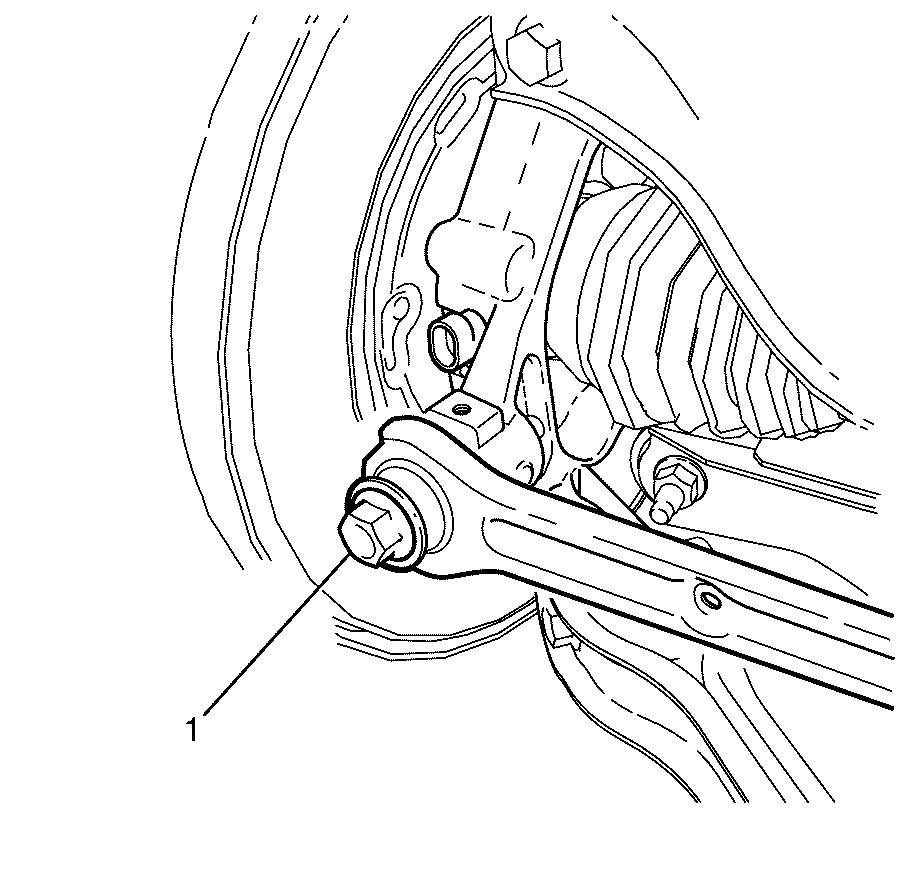
Important: The weight of the vehicle must be on a level surface and on all four wheels before fully tightening the nut.
Important: The suggested method to settle the rear suspension is with the wheels on the ground, open rear compartment lid and support the lid with a suitable brace. Using your hands press down hard on the rear compartment floor and release a number of times.
Tighten
Tighten the bolt to 140 N·m (103 lb ft).
Tighten
Tighten the nut to 175 N·m (129 lb ft).

