For 1990-2009 cars only
Tools Required
EN-48536 Frame Support Tool (Engine Lower 65mm Kit)
Removal Procedure
- Remove the trim plate. Refer to Console Trim Plate Replacement.
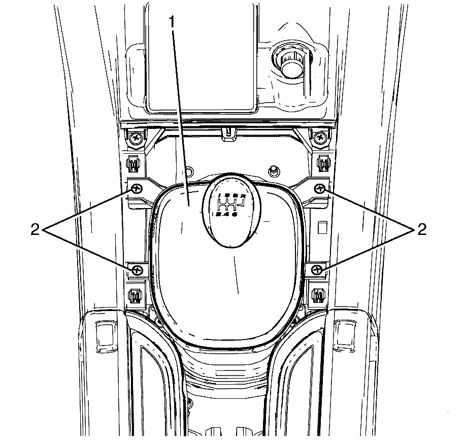
- Remove the gearshift lever boot to front console retaining screws (2).
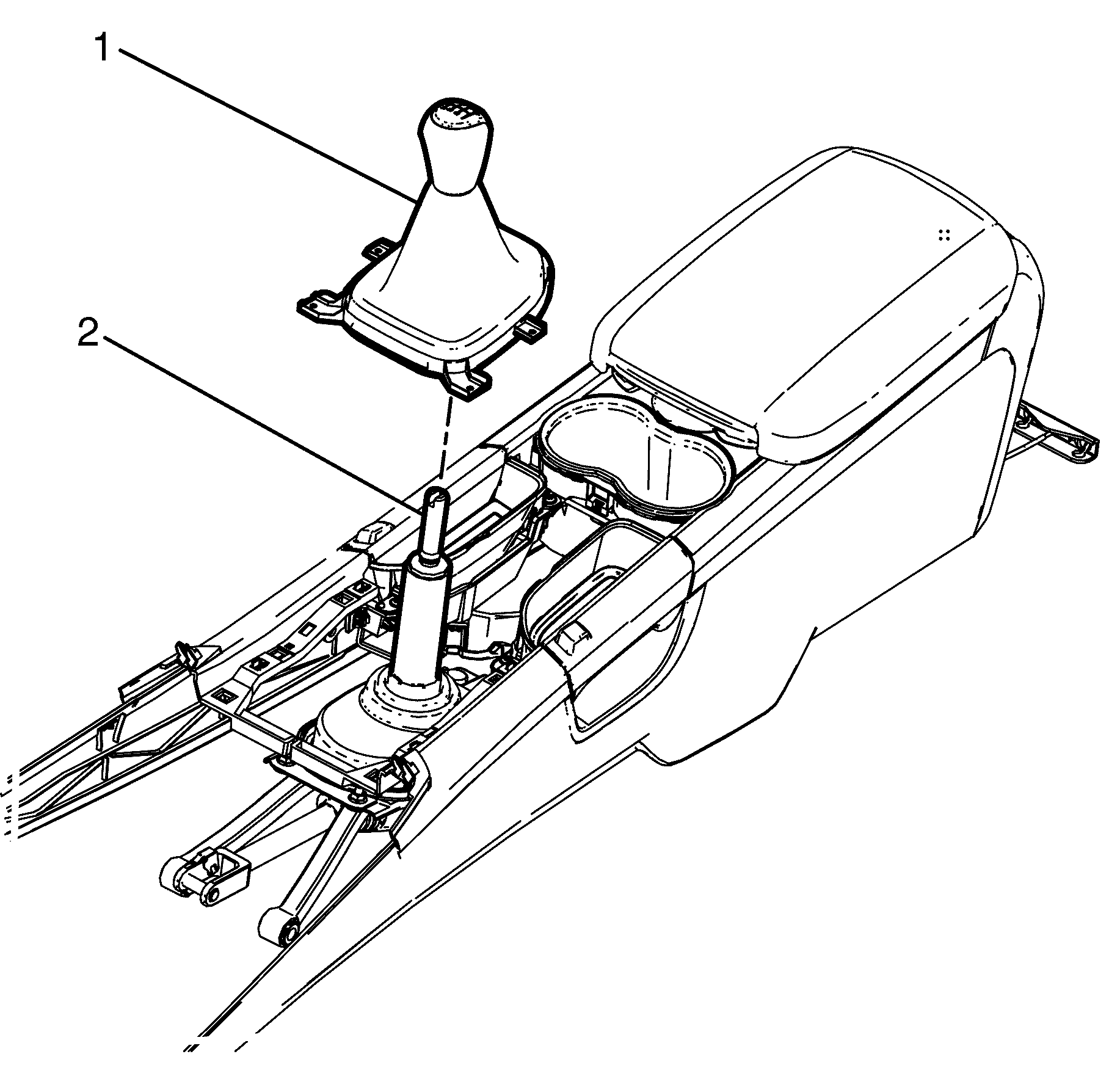
- Lift the gearshift lever boot (1) enough to enable a firm grasp to be made on the gearshift lever (2) with the left hand, then grasp the gearshift knob with the right.
- While rocking the knob sideways, and with an upward force applied, dislodge the knob retaining claws from the lever.
- Remove the gearshift lever knob and boot assembly, from the gearshift lever.
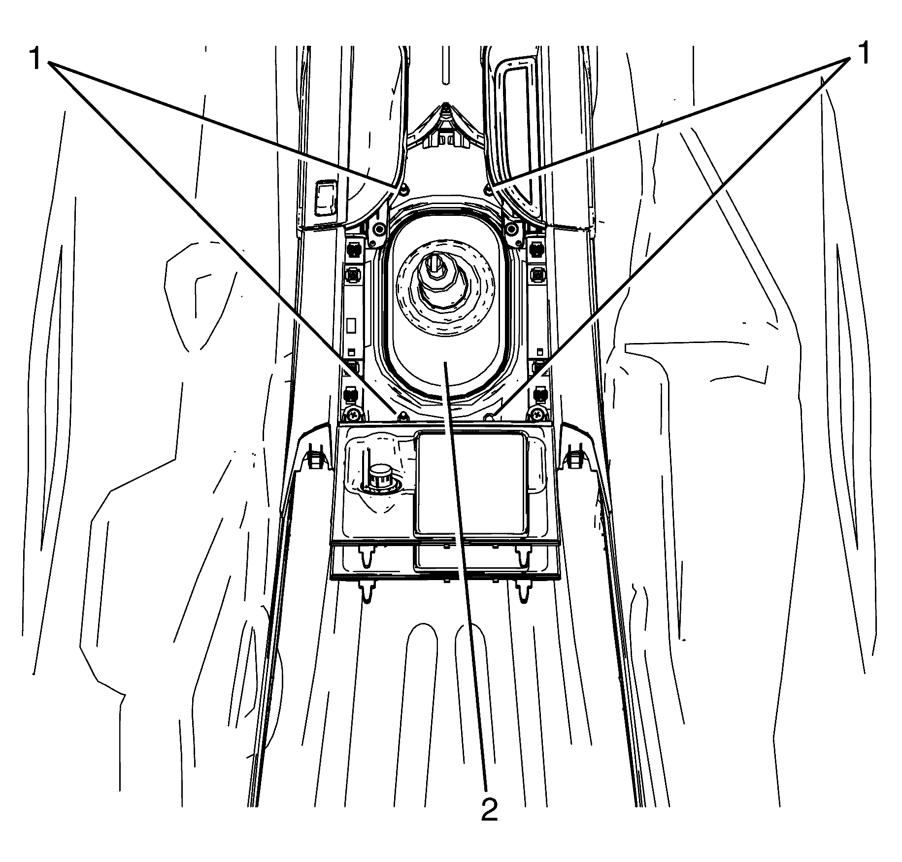
- Remove the shift control assembly to shift control adapter plate retaining nuts (1).
- Raise the vehicle. Refer to Lifting and Jacking the Vehicle.
- Remove the exhaust system. Refer to Exhaust System Replacement.
- Remove the propeller shaft. Refer to Propeller Shaft Replacement.
- Support the power train with a suitable jack or table.
- Support the transmission with a suitable jack.
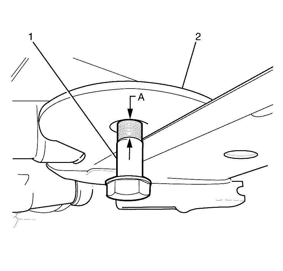
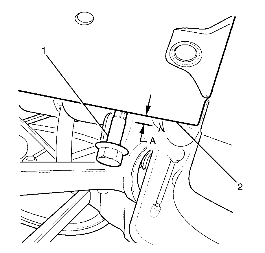
- Replace the front sub frame rear bolts and fit bolts from the EN-48536 .
- Install the retaining bolt (1) until the stepped shank (A) is two millimetres below sub frame (2).
- Replace the front sub frame front bolts and fit bolts from the EN-48536 .
- Install the retaining bolt (1) until the stepped shank (A) is two millimetres below chassis rail flange (2).
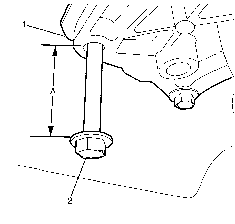
- Remove the left front and right rear retaining bolts from the transmission mount and install two retaining bolts from the EN-48536 in diagonal holes e.g Left hand front and Right hand rear.
- Install the retaining bolt (2) in until a 65 millimetre gap is achieved (A).
- Remove front sub frame middle bolts.
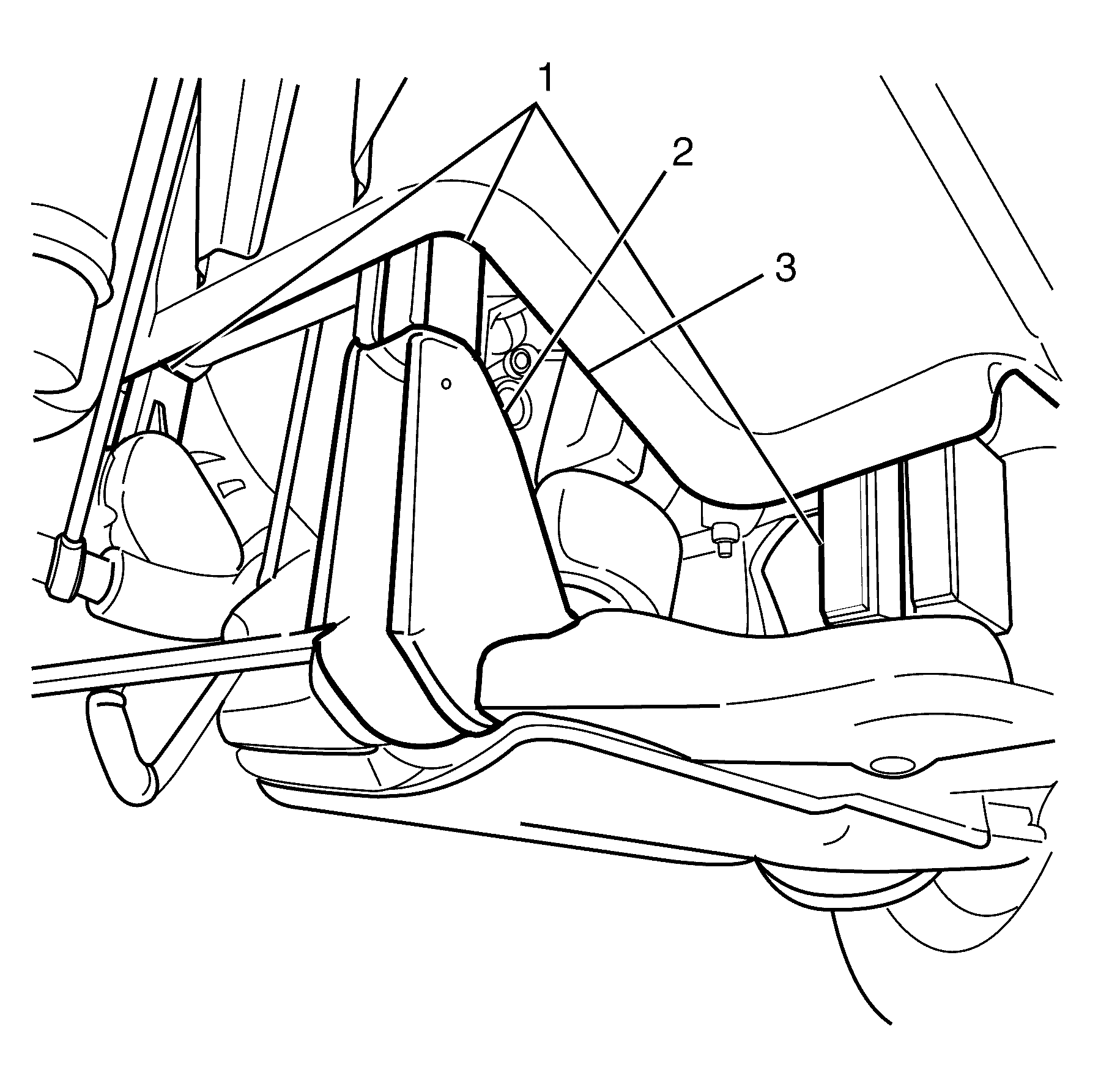
- Lower power train slowly until the subframe and transmission mount are resting on the bolts (2).
- Insert the 65 millimetre spacer blocks (1) from the EN-48536 between the subframe (2) and the chassis rails (3).
- Tension front sub frame front and rear retaining bolts.
- Install and tension middle sub frame retaining bolts.
- Remove suitable supporting jack.
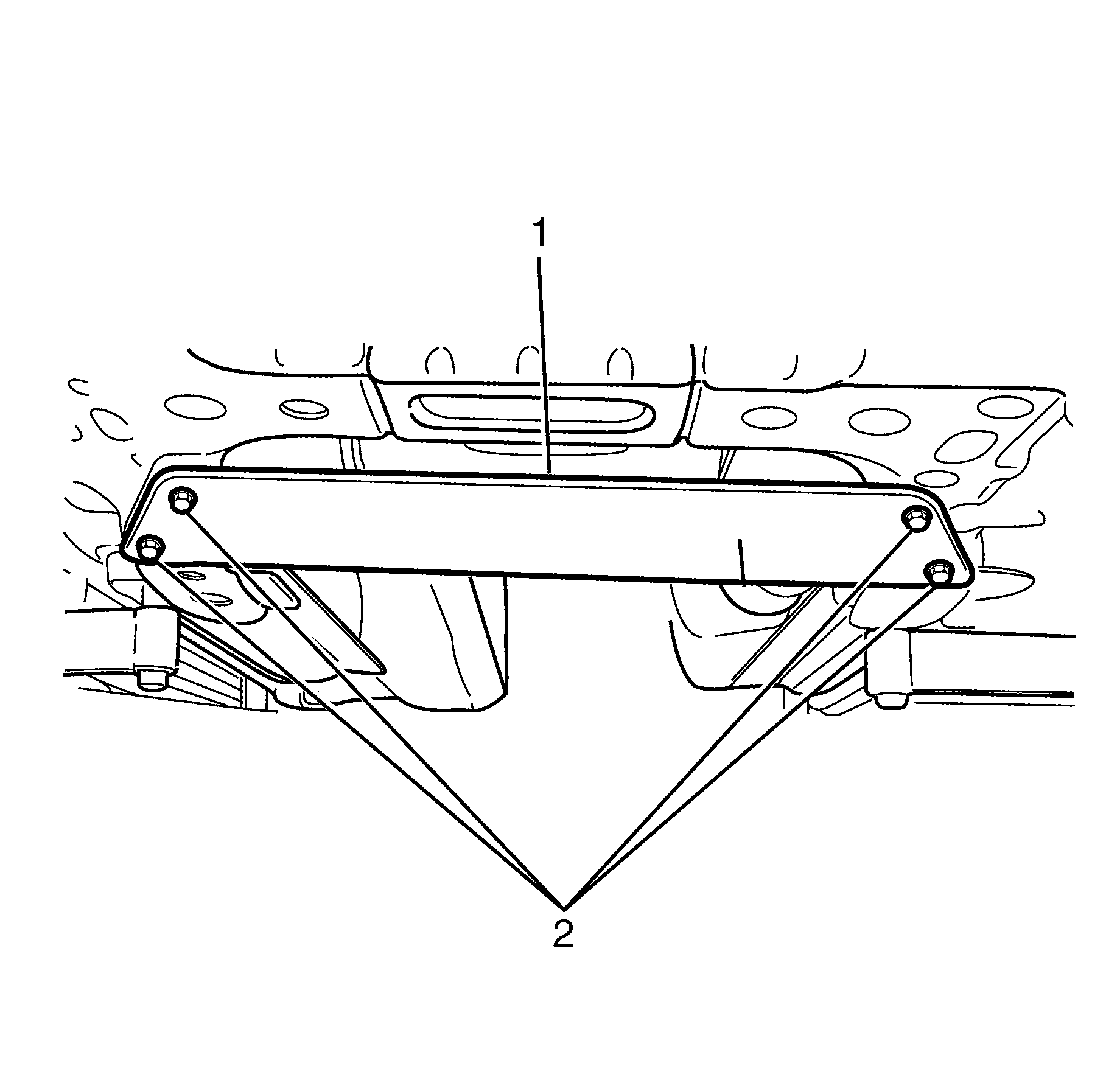
- Install the engine support plate (1) from the EN-48536 to the front sub frame (2).
- Install the engine support plate to front subframe retaining bolts (3).
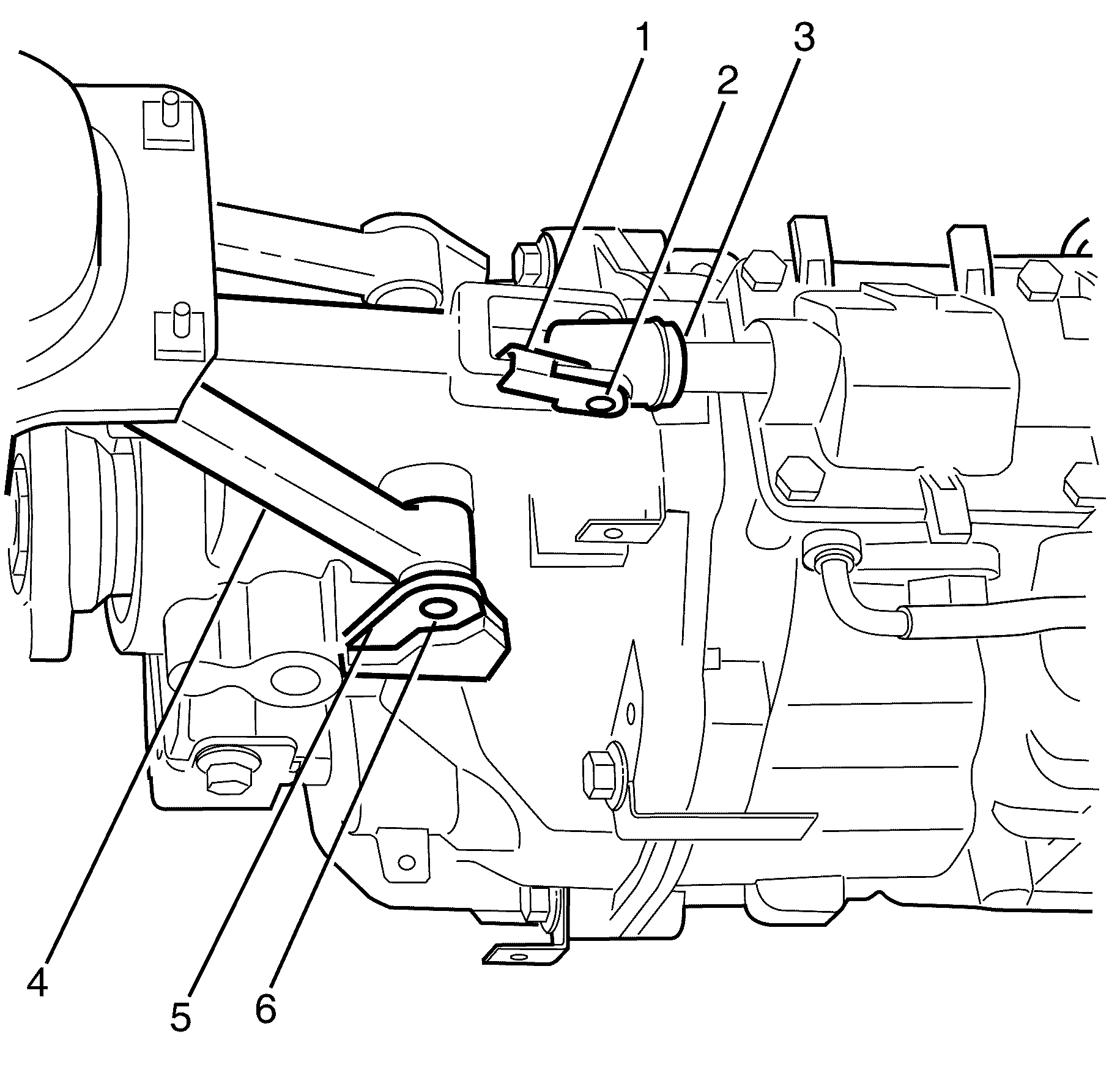
- Use a suitable tool to rotate the selector shaft rod retaining clip (1) upwards.
- Use a suitable tool to remove the selector shaft rod retaining pin (2) from the selector shaft rod (3).
- Use a suitable tool to rotate the shift control assembly rod retaining clip (5) upwards.
- Use a suitable tool to remove the retaining pin (6) from the shift control assembly rod (4). Repeat for opposite side.
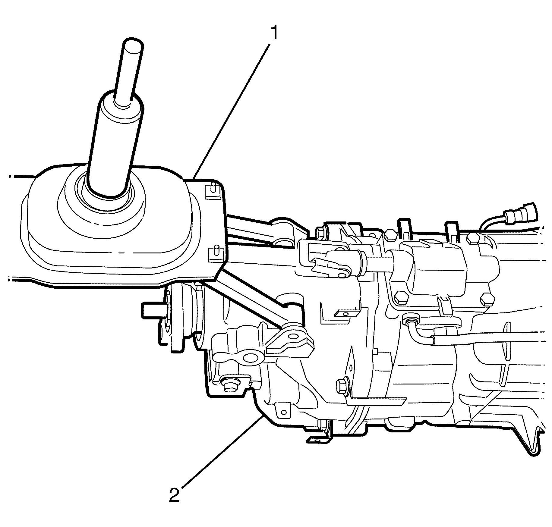
- Remove the shift control assembly (1) from the transmission (2).
Caution: Refer to Vehicle Lifting Caution in the Preface section.
Caution: Refer to Safety Glasses Caution in the Preface section.
Tighten
Tighten the bolts to 95 N·m (70 lb. ft).
Tighten
Tighten the bolts to 95 N·m (70 lb. ft).
Tighten
Tighten the bolts to 10 N·m (89 lb. in).
Installation Procedure
- Install the shift control assembly (1) to the transmission (2).
- Use a suitable tool to install the retaining pin (6) to the shift control assembly rod (4).
- Rotate the shift control assembly rod retaining clip (5) downwards to lock the retaining pin (6). Repeat for opposite side.
- Use a suitable tool to install the retaining pin (2) to the selector shaft rod (3).
- Rotate the selector shaft rod retaining clip (1) downwards to lock the retaining pin (2).
- Support the power train with a suitable jack or table.
- Support the transmission with a suitable jack.
- Loosen the EN-48536 retaining bolt (1) until the stepped shank (A) is two millimetres below subframe (2).
- Loosen the EN-48536 retaining bolt (1) until the stepped shank (A) is two millimetres below the subframe (2).
- Loosen the EN-48536 transmission mount to body retaining bolts (2) in the diagonal holes (ie. Left hand front and Right hand rear).
- Remove EN-48536 front sub frame middle bolts.
- Remove the EN-48536 six 65 millimetre spacer blocks (1) between subframe (2) and chassis rails (3).
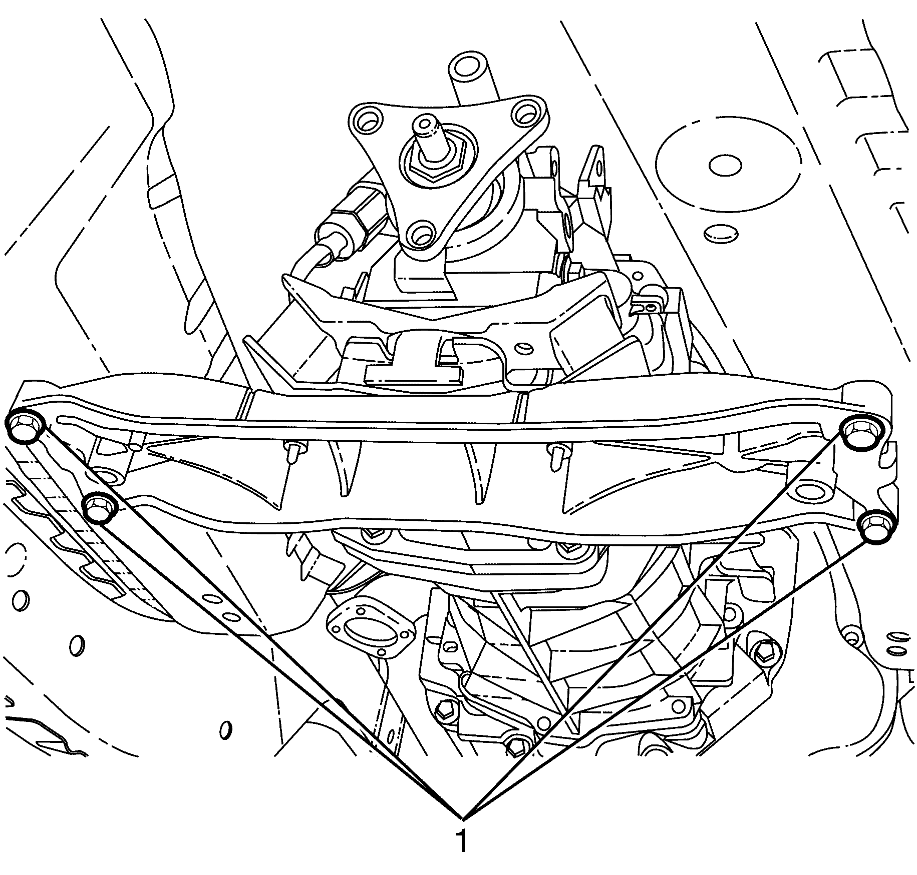
- Install the front sub frame to chassis rail retaining bolts.
- Install the rear sub frame to chassis rail retaining bolts.
- Install the centre sub frame to chassis rail retaining bolts.
- Install the transmission mount to body retaining bolts (1).
- Raise the vehicle.
- Remove supporting jack or table.
- Remove the EN-48536 engine support plate (1) to front sub frame retaining bolts (2).
- Remove the EN-48536 engine support plate from the vehicle.
- Install the propeller shaft. Refer to Propeller Shaft Replacement.
- Install the exhaust system. Refer to Exhaust System Replacement.
- Lower the vehicle.
- Install the shift control assembly to shift control adapter plate retaining nuts (1).
- Install the gearshift lever knob and boot assembly (1) to the gearshift lever.
- Align the gearshift lever knob to the gearshift lever (2).
- Apply pressure to the top of the gearshift knob to engage into the gearshift lever.
- Install the gearshift lever boot to front console retaining screws (2).
- Install the trim plate. Refer to Console Trim Plate Replacement.


Tighten
Tighten the bolts to 95 N·m (70 lb. ft).
Tighten
Tighten the bolts to 95 N·m (70 lb. ft).
Tighten
Tighten the bolts to 95 N·m (70 lb. ft).
Tighten
Tighten the bolts to 58 N·m (43 lb ft).


Tighten
Tighten the bolts to 12 N·m (106 lb in).


Tighten
Tighten the screws to 2 N·m (18 lb in).
