General Information
Manual transmissions are identified by the number of forward gears and the measured distance between the centerline of the output shaft and the counter gear.
The Tremec T56 six speed manual transmission primarily consists of a four piece aluminium alloy construction, comprising a clutch housing bolted to a front adaptor plate, transmission case and extension housing.
The ‘T56’ manual transmission is a fully synchronised unit, including reverse gear, with blocking ring type synchronisers. A triple piece synchroniser assembly is fitted to first and second gears and two piece assemblies are fitted to third, fourth, fifth and sixth gears. Reverse gear is fitted with a single piece blocking ring.
The input shaft, mainshaft and countershaft gears are all supported by taper roller bearings. A parallel roller supports the rear of the mainshaft, while all constant mesh gears have caged needle roller bearings.
During disassembly, the major number of gear train components and shift mechanism remain on the transmission front adaptor plate.
The gear ratios are as follows:
Gear | M10 Ratio (:1) |
|---|---|
FIRST | 3.01 |
SECOND | 2.07 |
THIRD | 1.43 |
FOURTH | 1.00 |
FIFTH | 0.84 |
SIXTH | 0.57 |
REVERSE | 3.28 |
Synchroniser Assemblies
Each of the four synchroniser hubs are splined to their respective shafts and secured by a snap ring. All synchromesh blocking rings have a carbon fibre frictional material and are brass, except for 1st and 2nd gears.
The blocking rings used on 1st and 2nd gears are of a double cone construction, with carbon fibre frictional material on each side of the inner member. The purpose of the synchroniser assemblies is to permit clutching to the required gear.
During synchroniser operation, the synchroniser ring is moved into engagement by the appropriate fork, carrying with it, three spring loaded synchroniser inserts, located in slots in the synchroniser hub.
The synchroniser ring, together with the inserts, is moved along the hub, placing a load on the three lugs of the blocking ring.
This initial force is sufficient to seat the blocking ring and start pre-synchronisation because of the friction between the cone on the constant mesh gear and the blocking ring.
At this stage, gear engagement is prevented as long as there is a difference in speed between the mating surfaces of the blocking ring and cone of the constant mesh gear. As the speeds between the blocking ring and the gear cone become synchronised, the teeth on the blocking ring and gear cone line up with the internal splines of the ring, allowing the ring to engage the teeth on the gear being engaged, completing gear selection.
Reverse Gear
The reverse idler gear is in constant mesh with the countershaft gear and the reverse gear, splined to the mainshaft. When reverse gear is engaged, the reverse synchromesh ring engages the reverse constant mesh gear, completing the selection.
Bearing Support
All shafts in the transmission are supported by taper roller bearings, except for a parallel roller bearing at the rear of the mainshaft.
The input shaft gear and countershaft gear extension bearing cups are a sliding fit in their respective housings. Selective shims are located under each of the bearing cups to control bearing pre-load or end float (for the countershaft).
Each of the constant mesh gears is supported by caged needle roller bearings, except for the reverse idler gear that has a twin, caged needle roller bearing running on the reverse idler gear shaft.
Lubrication
Lubrication of all internal components is by splash feed, provided by the rotating countershaft gear assembly.
Selector Mechanism
The floor mounted, gearshift control lever operates through a remote lever arrangement onto a single rail mechanism which extends into the transmission rear case. The 1st/2nd, 3rd/4th, 5th/6th and reverse shift shaft rails are all supported at each end, in the adaptor plate, transmission case or extension housing.
A shift interlock system, prevents engagement of more than one gear at a time. The system consists of a selector pin and interlock plate mounted on the 1st/2nd and 3rd/4th selector shaft rail.
When any gear is selected, the selector pin is aligned with the particular shift fork link or shift lever, with 5th/6th and reverse gears. As this selector pin slides within the interlock plate, only the gear selected can be engaged.
Reverse Lockout
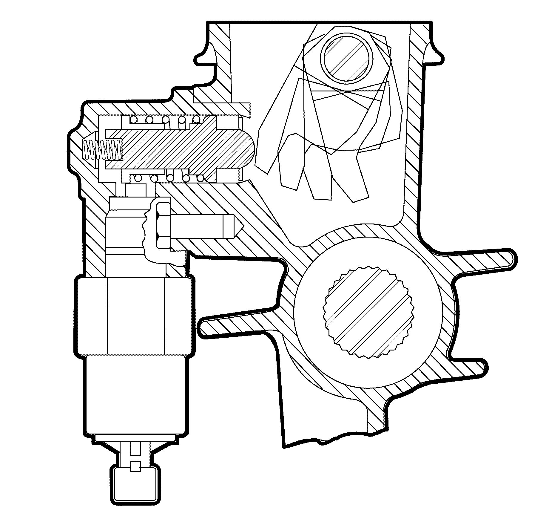
The transmission is also fitted with a reverse lockout solenoid assembly that prevents the selection of reverse gear, above road speeds of 5 km/h (3 mph) or more.
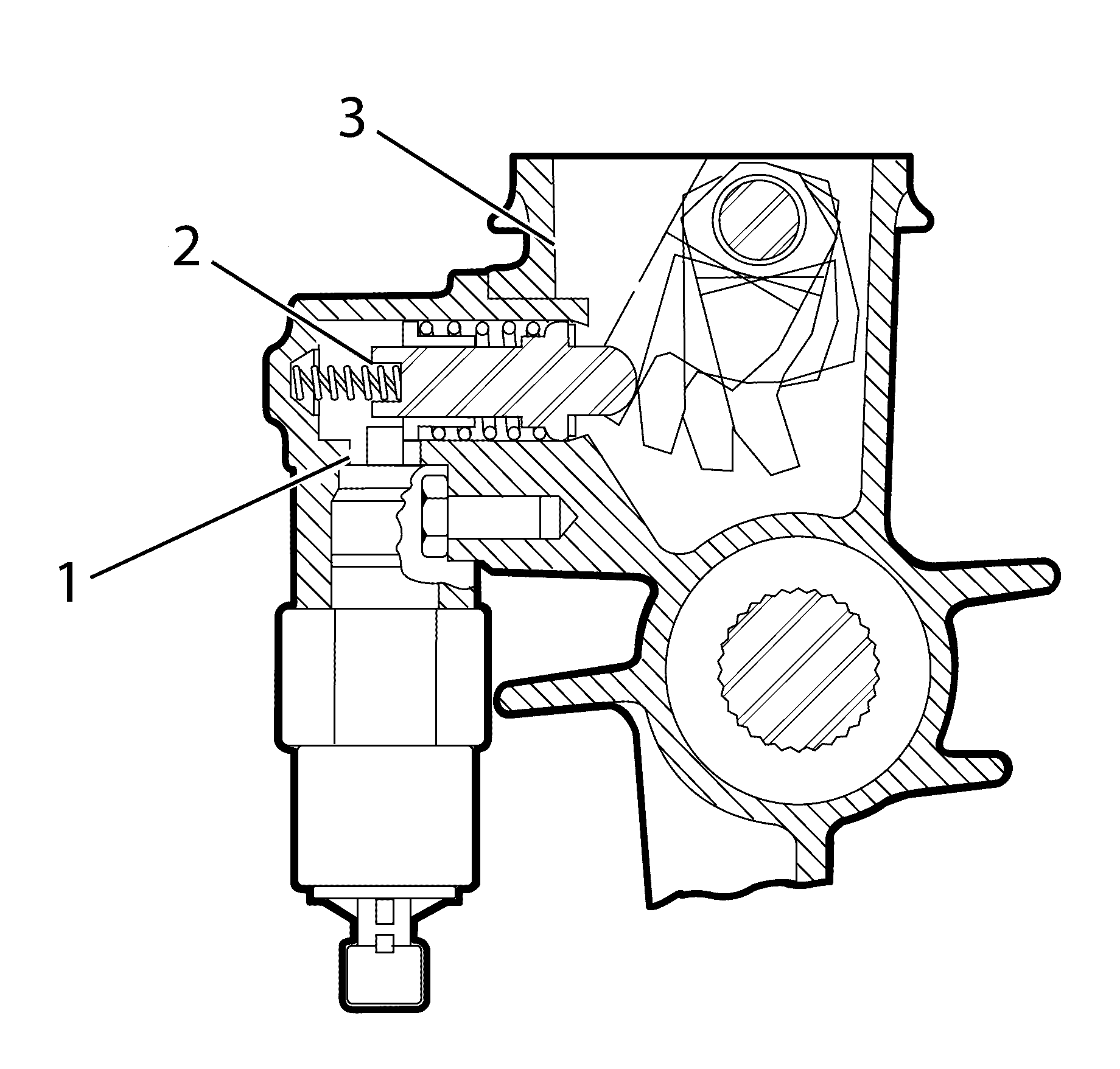
Above road speeds of 5 km/h (3 mph) or more, the Powertrain Control Module (PCM), activates the solenoid plunger (1) which blocks the movement of the spring loaded, reverse lockout plunger (2). When activated, the rear offset lever (3) is blocked from rotating to the reverse selection position.
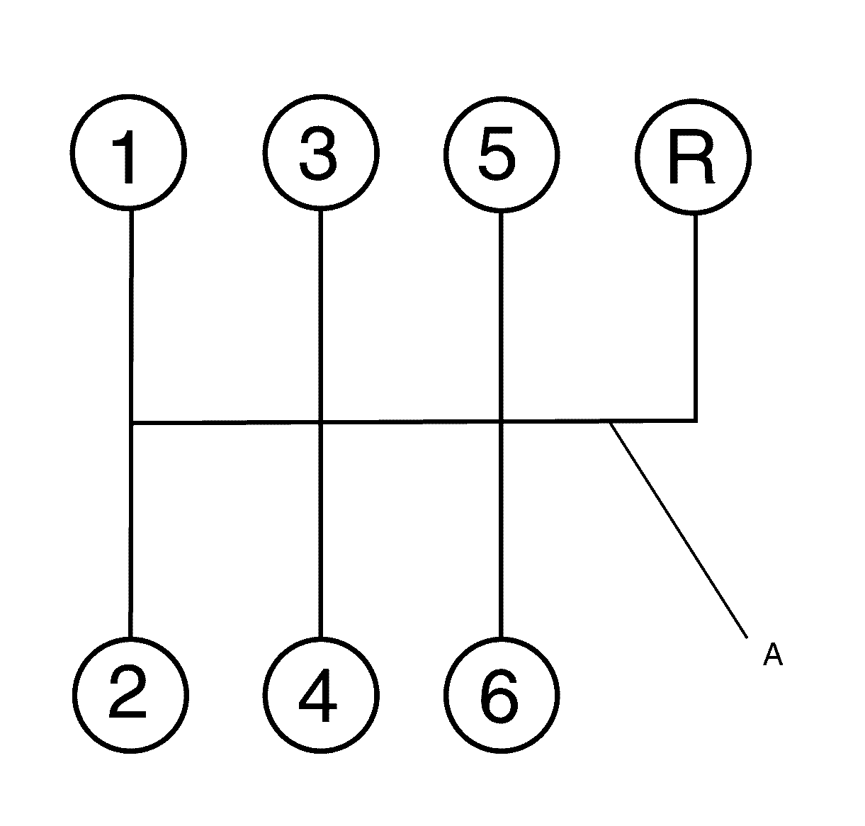
Point (A) of the shift pattern indicates how reverse gear can be inhibited by the reverse lockout solenoid assembly.
Transmission Power Flows
The input shaft drive gear, third, second and first speed gears are in constant mesh with the countershaft gear. The reverse drive gear rotates with the countershaft gear.
Therefore, when the engine is running with the clutch engaged, engine torque is transferred to the input shaft drive gear and through the countershaft gear to the third, second, first speed and reverse gears at all times.
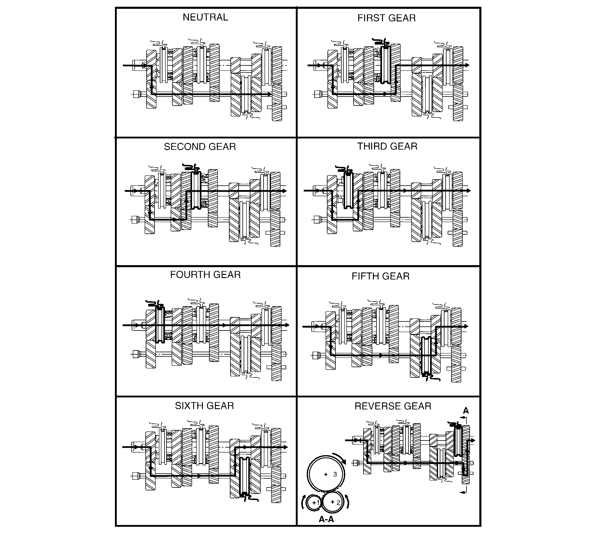
Neutral
In neutral, with the clutch engaged, the input shaft drive gear turns the countershaft gear. The countershaft gear turns the constant mesh gears of 3rd, 2nd, 1st and reverse gears because no synchroniser assemblies are engaged. As these constant mesh gears are supported on roller bearings, they will also rotate with the countershaft gear. As the 5th/6th compound gear is splined to the mainshaft, these constant mesh gears will remain stationery while the vehicle is stopped.
First Gear
In first gear, the first/second speed synchroniser ring is moved rearward to engage the first speed gear, which is being turned by the countershaft gear. Because the first/second speed synchroniser hub is splined to the mainshaft, torque is transferred to the mainshaft from the first speed gear through the synchroniser ring and hub, at a speed reduction of 3.01:1.
Second Gear
In second gear, the first/second speed synchroniser ring is moved forward to engage the second speed gear, which is being turned by the countershaft gear. Because the first/second speed synchroniser hub is splined to the mainshaft, torque is transferred to the mainshaft from the second speed gear through the synchroniser ring and hub, at a speed reduction of 2.07:1.
Third Gear
In selecting third gear, the first/second speed synchroniser ring moves to the neutral position and the third/fourth speed synchroniser ring is moved rearward to engage the third speed gear. As this gear is being turned by the countershaft gear, the engagement of the ring with the third speed gear, torque is transferred to the mainshaft because the third/fourth speed synchroniser hub is splined to the mainshaft. The mainshaft the turns at a speed reduction of 1.43:1.
Fourth Gear
In fourth gear, the third/fourth speed synchroniser ring is moved forward to engage the input shaft drive gear. This engagement of the input shaft drive gear with the third/fourth synchroniser ring and hub assembly, transfers torque directly to the mainshaft. While the countershaft gear is still rotating, no torque transfer takes place but the spinning gear continues to lubricate the internal transmission components by the ‘splash’ method. As the mainshaft is effectively joined to the input shaft, the drive is direct with a ratio of 1.00:1.
Fifth Gear
In fifth gear, which is the first of the overdrive ratios , the first/second and third/fourth speed synchroniser rings must be in the neutral position. The fifth/sixth speed synchroniser ring is moved rearward to engage the fifth speed drive gear, supported on the countershaft gear by a caged needle roller bearing. This engagement of the ring with the fifth speed constant mesh gear, allows torque to be transferred from the countershaft gear to the mainshaft, via the splined synchromesh hub and the splined fifth/sixth speed compound driven gear. This speed generates an overdrive ratio of 0.84:1.
Sixth Gear
In sixth gear, the fifth/sixth speed synchroniser ring is moved forward to engage the sixth speed drive gear, supported on the countershaft gear by a caged needle roller bearing. This engagement of the ring with the sixth speed constant mesh gear, allows torque to be transferred from the countershaft gear to the mainshaft, via the splined synchromesh hub and the splined fifth/sixth speed compound driven gear. This speed generates an overdrive ratio of 0.57:1.
