For 1990-2009 cars only
Removal Procedure
- Remove the control valve body cover. Refer to Control Valve Body Cover Replacement .
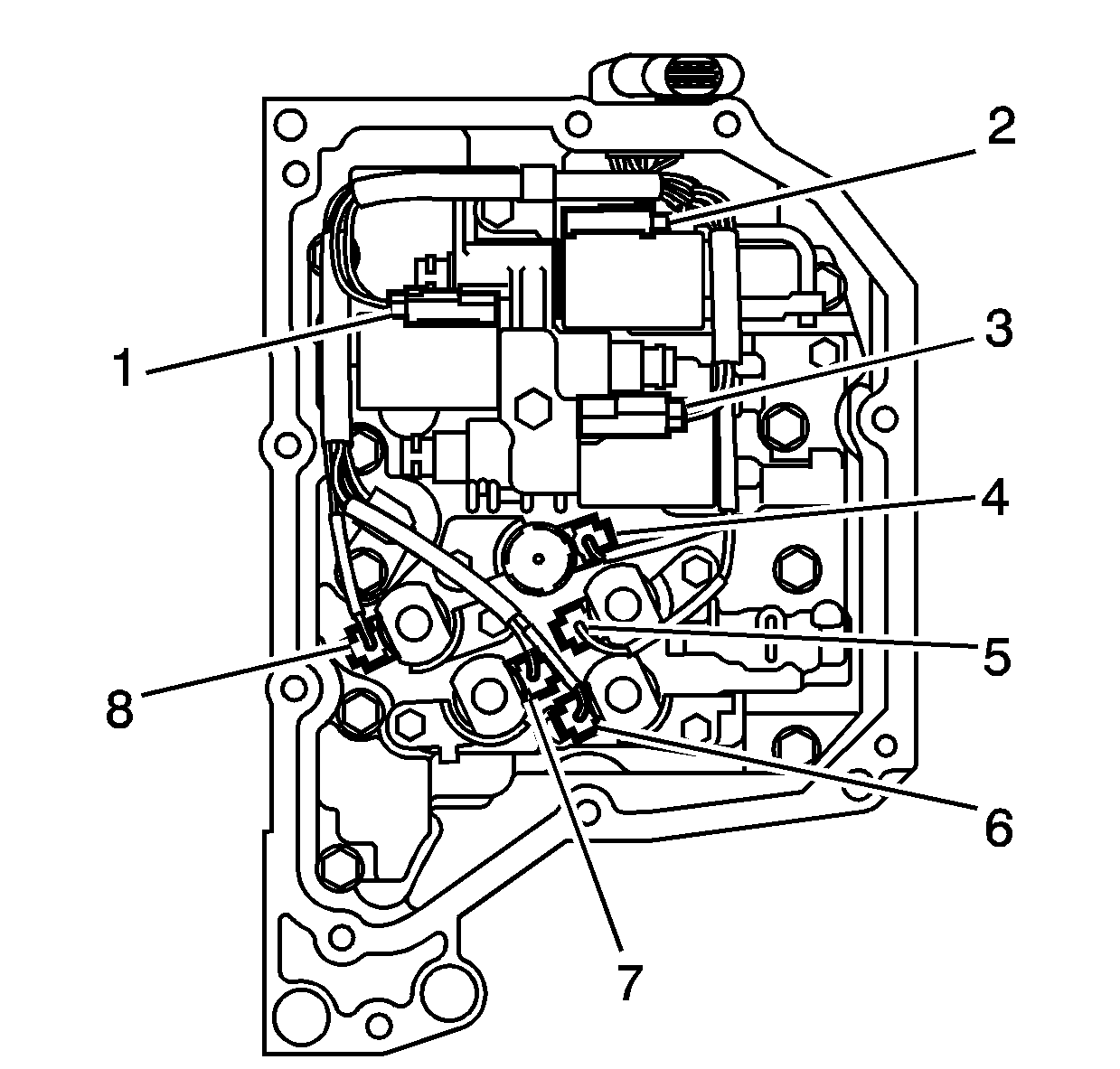
- Disconnect the wiring harness connectors (1-8).
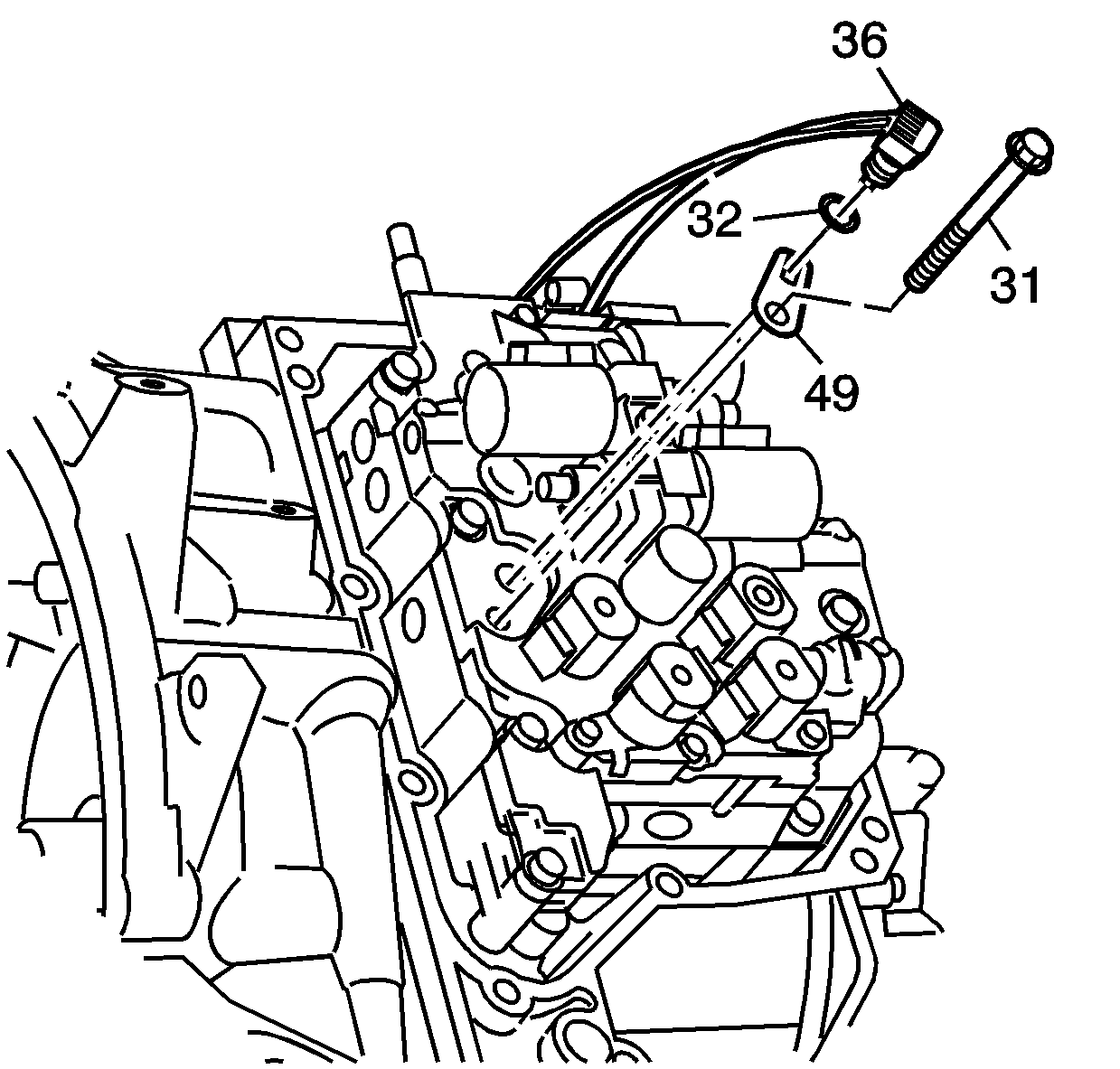
- Remove the fluid temperature sensor bolt (31).
- Remove the fluid temperature sensor clamp (49).
- Remove the fluid temperature sensor (36) and the O-ring (32) from the control valve body.
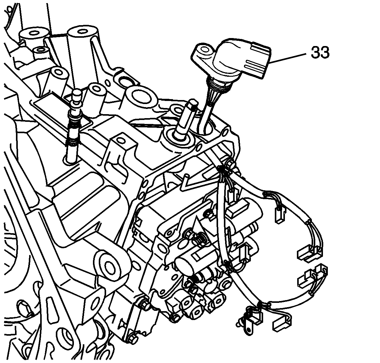
- Remove the wiring harness (33) from the automatic transaxle wiring harness clip.
- With a twisting motion remove the complete wiring harness assembly.
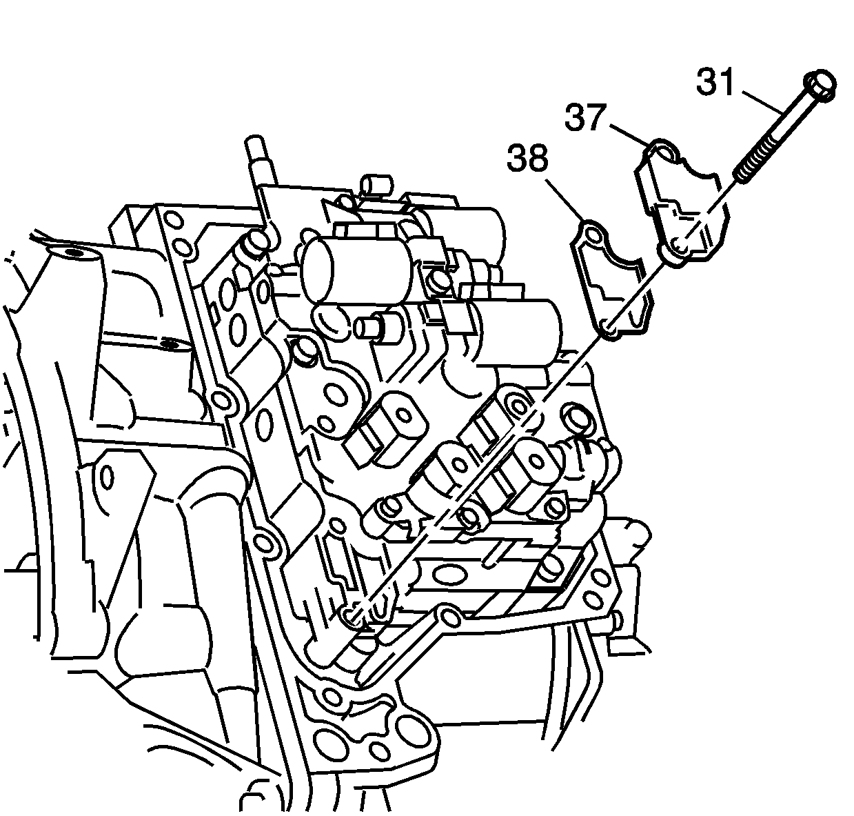
- Remove the 2 control valve body bolts/screws (31), control valve body fluid passage cover (37) and gasket (38).
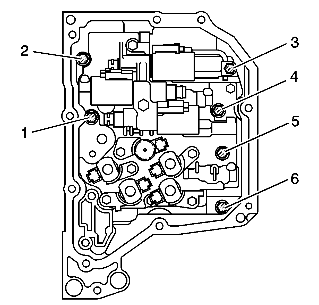
- Remove the 6 control valve body mounting bolts/screws (1-6).
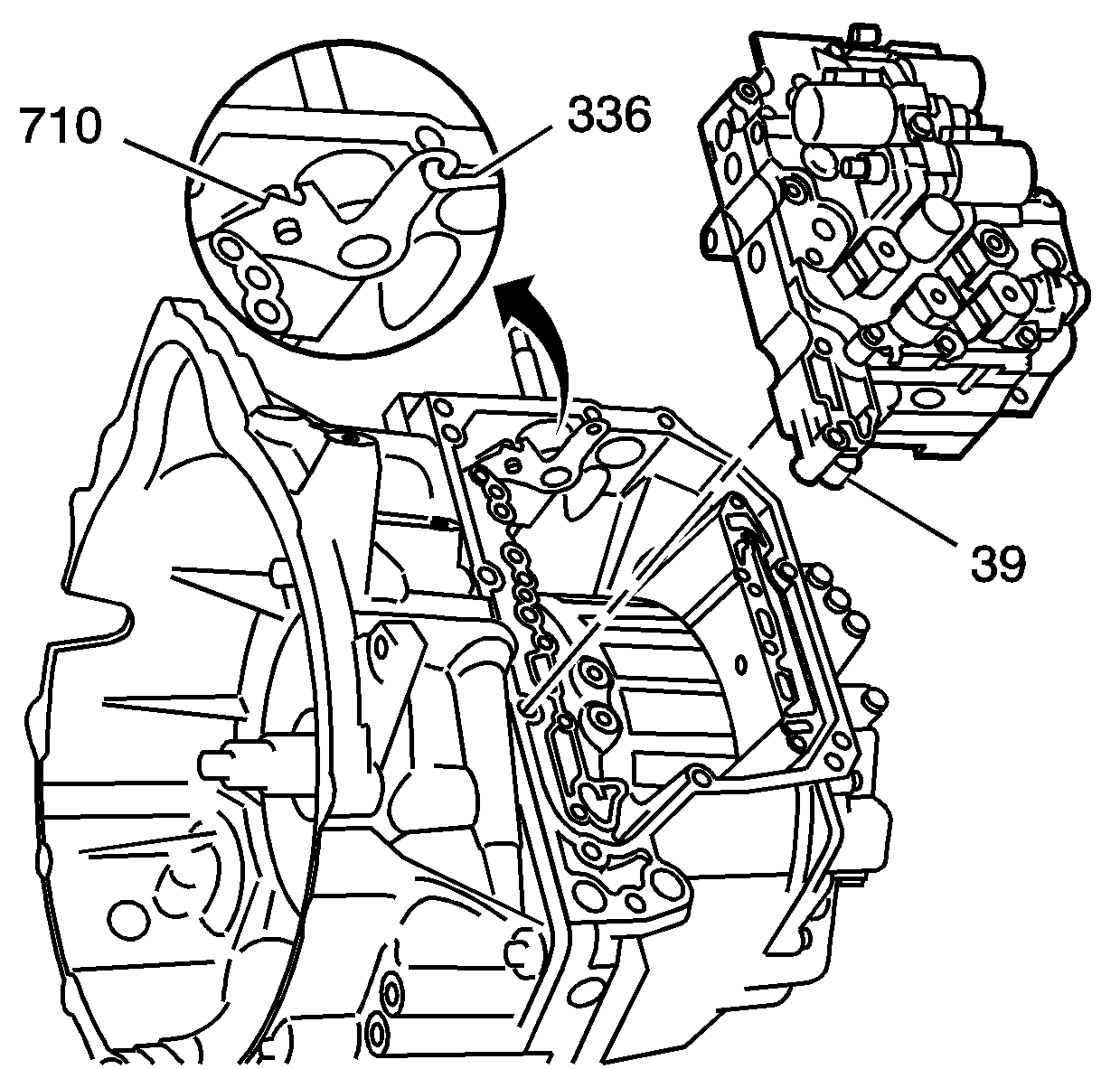
- While holding the control valve body assembly, disconnect the manual shift detent lever assembly (710) from the manual valve link (336).
- Move the detent lever assembly clockwise for ease of removing the manual valve.
- Remove the control valve body assembly (39).
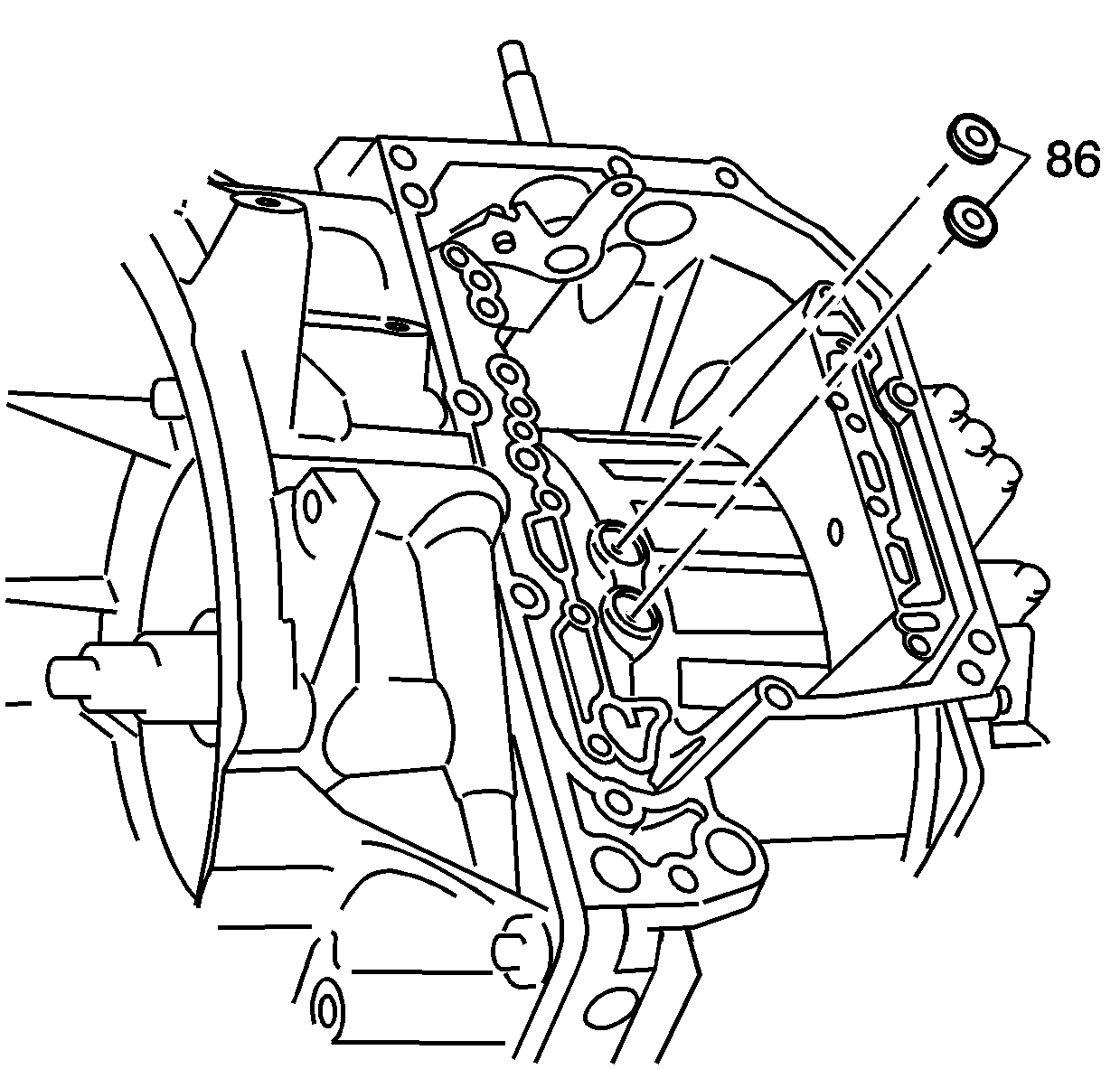
- Remove the 2 transaxle case fluid passage seals (86).
Important: Place the transaxle in neutral (N).
Installation Procedure
- Install 2 new transaxle case fluid passage seals (86) into the transaxle case fluid ports.
- While holding the control valve body assembly (39), connect the manual valve link (336) to the manual shift detent lever assembly (710).
- Install the 6 control valve body assembly to transaxle case bolts and hand tighten.
- Tighten the control valve body assembly-to-transaxle case bolts in sequence.
- Install a new control valve body fluid passage cover gasket (38).
- Install the control valve body fluid passage cover (37).
- Install the 2 control valve body bolts (31).
- Apply automatic transaxle fluid to a new transaxle wiring connector O-ring seal (46).
- Install a new transaxle wiring connector O-ring seal (46) onto the transaxle wiring harness assembly (33).
- Install the transaxle wiring harness assembly (33) into the transaxle case through the wiring harness bore.
- Apply automatic transaxle fluid to a new transaxle fluid temperature sensor O-ring seal (32).
- Install a new transaxle fluid temperature sensor O-ring seal (32) into the groove of the transaxle fluid temperature sensor (36).
- Install the transaxle fluid temperature sensor (36) into the front control valve body fluid temperature sensor bore.
- Install the transaxle fluid temperature sensor clip (49).
- Install the fluid temperature sensor bolt (31).
- Connect the 8 solenoid wire connectors as follows:
- Install the control valve body cover. Refer to Control Valve Body Cover Replacement .
- Perform the transmission adaptive learn procedure. Refer to Transmission Adaptive Learn .


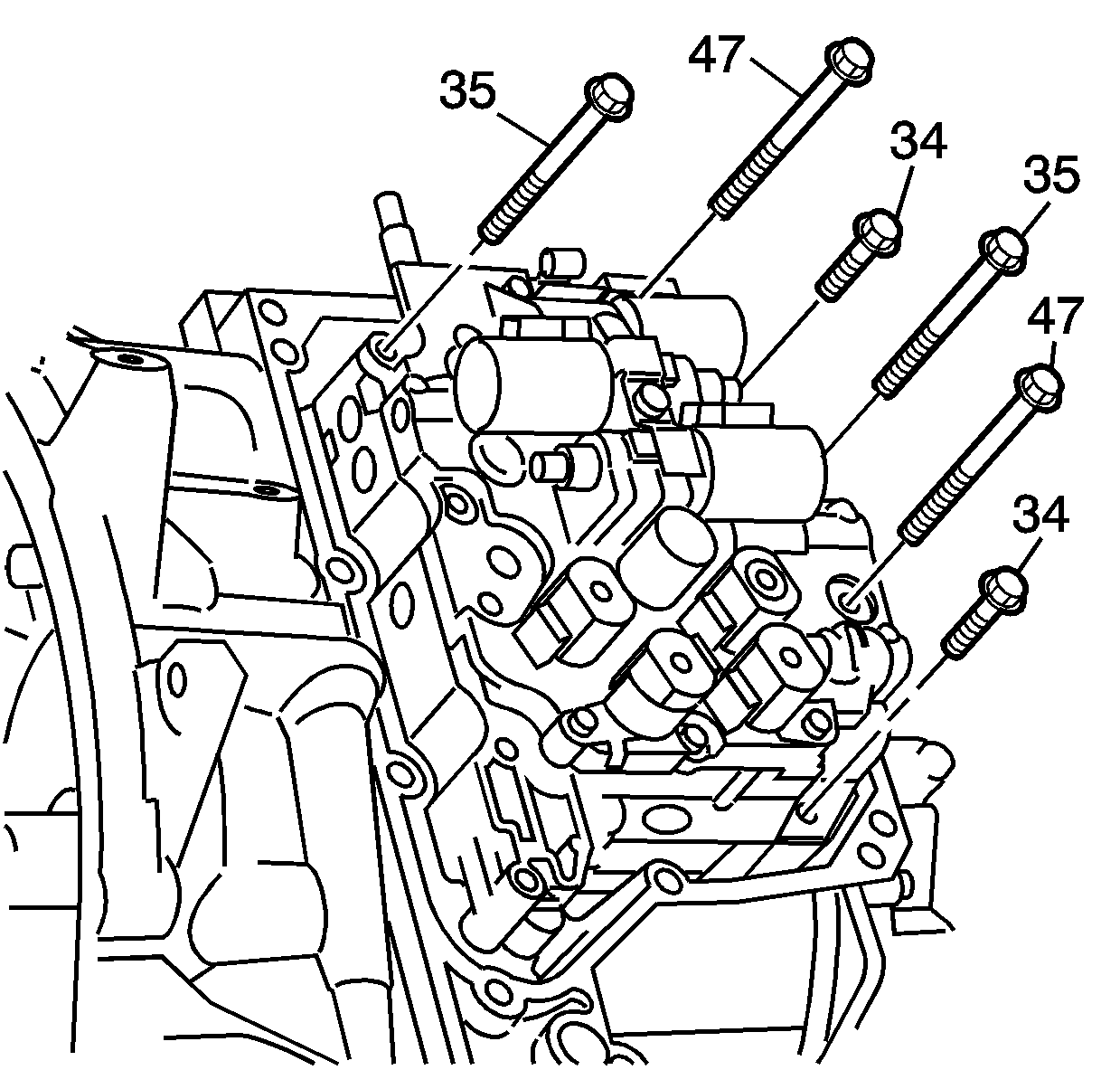
Notice: Refer to Fastener Notice in the Preface section.
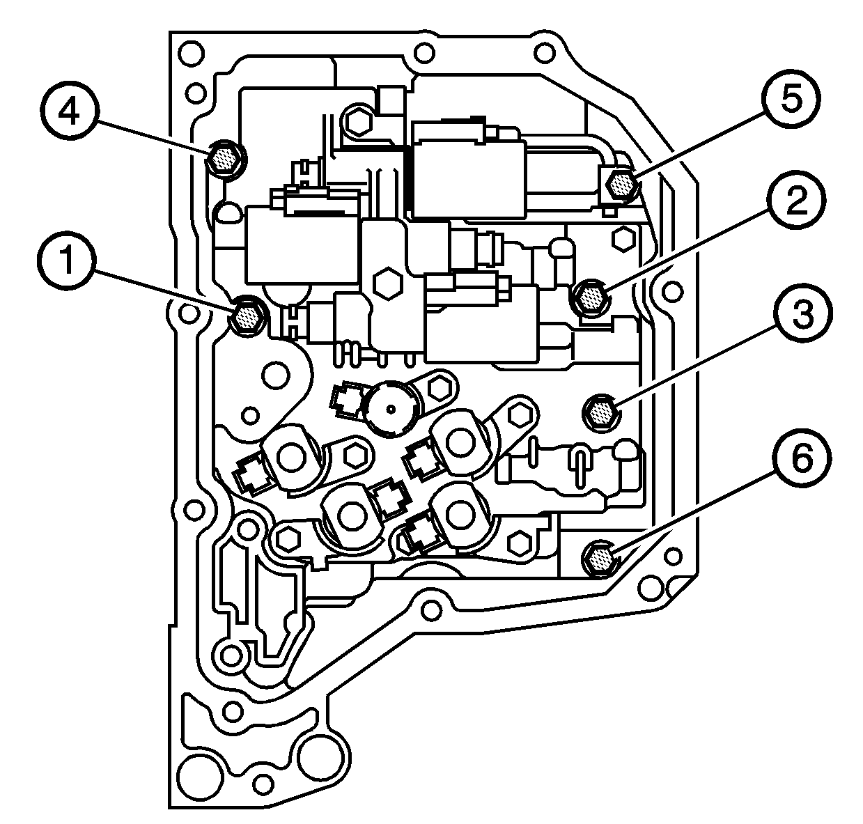
Tighten
Tighten the bolts to 10 N·m (89 lb in).

Tighten
Tighten the bolt to 10 N·m (89 lb in).
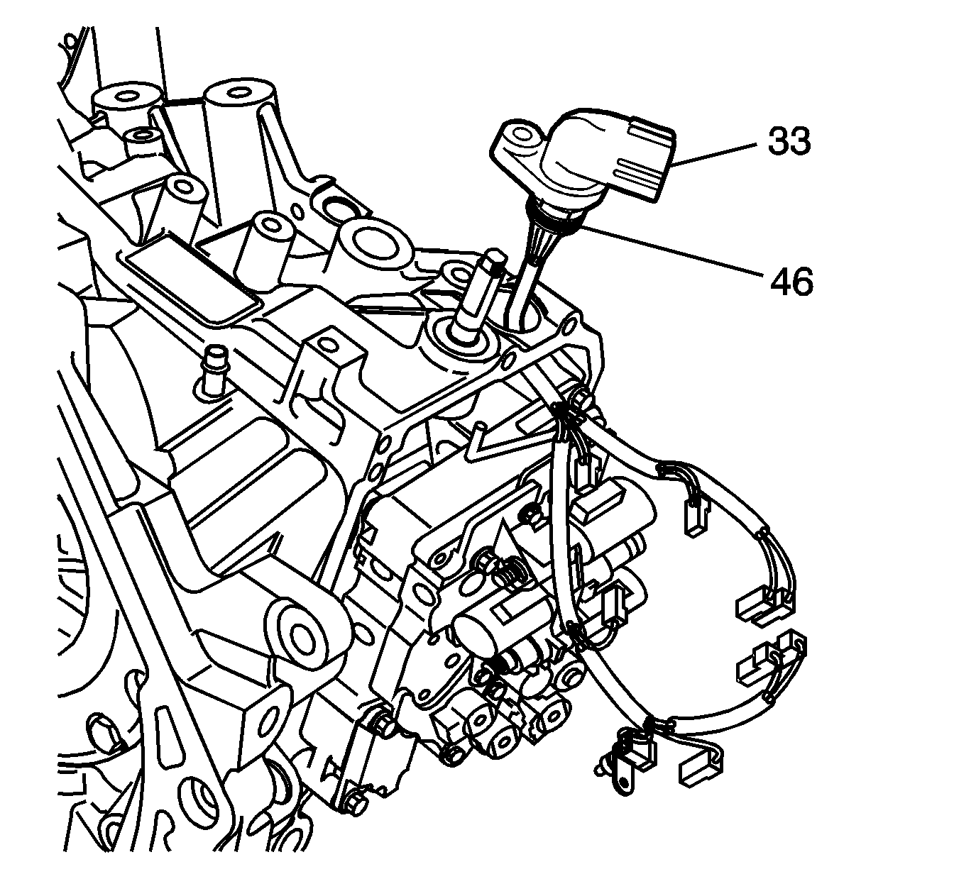

Tighten
Tighten the bolt to 10 N·m (89 lb in).
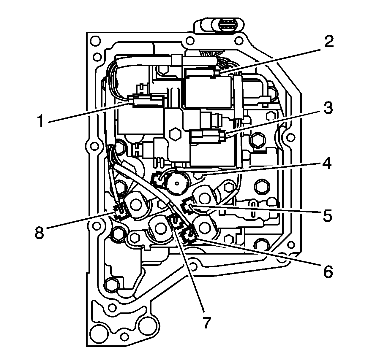
| • | 1 |
| • | 2 |
| • | 3 |
| • | 4 |
| • | 5 |
| • | 6 |
| • | 7 |
| • | 8 |
