For 1990-2009 cars only
Body Control Module Replacement C100/Long Body
Removal Procedure
- Disconnect the negative battery cable.
- Remove the radio. Refer to Radio Replacement .
- Remove the HVAC control assembly. Refer to Heater and Air Conditioning Control Replacement .
- Remove the shift lever control assembly or housing. For Aisin-51LE Automatic transaxle. Refer to Transmission Control Replacement for D33 Manual Transaxle. Refer to Transmission Control Replacement .
- Disconnect the electrical connectors.
- Remove the body control module (BCM).
Caution: Refer to Battery Disconnect Caution in the Preface section.
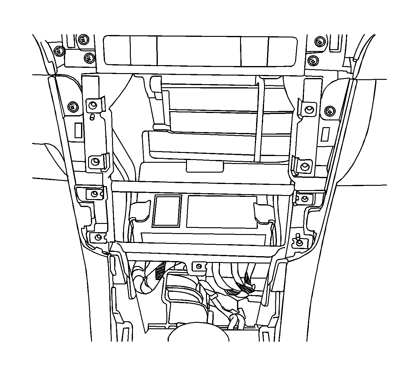
Installation Procedure
- Install the BCM.
- Connect the electrical connectors.
- Install the shift lever control assembly or housing. For Aisin-51LE Automatic transaxle. Refer to Transmission Control Replacement for D33 Manual Transaxle. Refer to Transmission Control Replacement .
- Install the HVAC control assembly. Refer to Heater and Air Conditioning Control Replacement .
- Install the radio. Refer to Radio Replacement .
- Connect the negative battery cable.

Body Control Module Replacement C105/Short Body
Removal Procedure
- Disconnect the negative battery cable.
- Remove the radio. Refer to Radio Replacement .
- Remove the HVAC control assembly. Refer to Heater and Air Conditioning Control Replacement .
- Remove the shift lever control assembly or housing. Refer to Transmission Control Replacement for the Aisin-51LE transaxle or Transmission Control Replacement for the D33 transaxle.
- Disconnect the electrical connectors.
- Remove the body control module (BCM).
Caution: Refer to Battery Disconnect Caution in the Preface section.
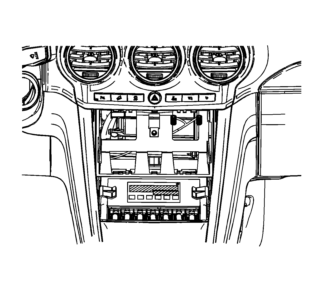
Installation Procedure
- Install the body control module (BCM).
- Connect the electrical connectors.
- Install the shift lever control assembly or housing. Refer to Transmission Control Replacement for the Aisin-51LE transaxle or Transmission Control Replacement for the D33 transaxle.
- Install the radio. Refer to Radio Replacement .
- Install the HVAC control assembly. Refer Heater and Air Conditioning Control Replacement .
- Connect the negative battery cable.

Body Control Module Replacement X-BCM C100/Long Body
Removal Procedure
- Disconnect the negative battery cable.
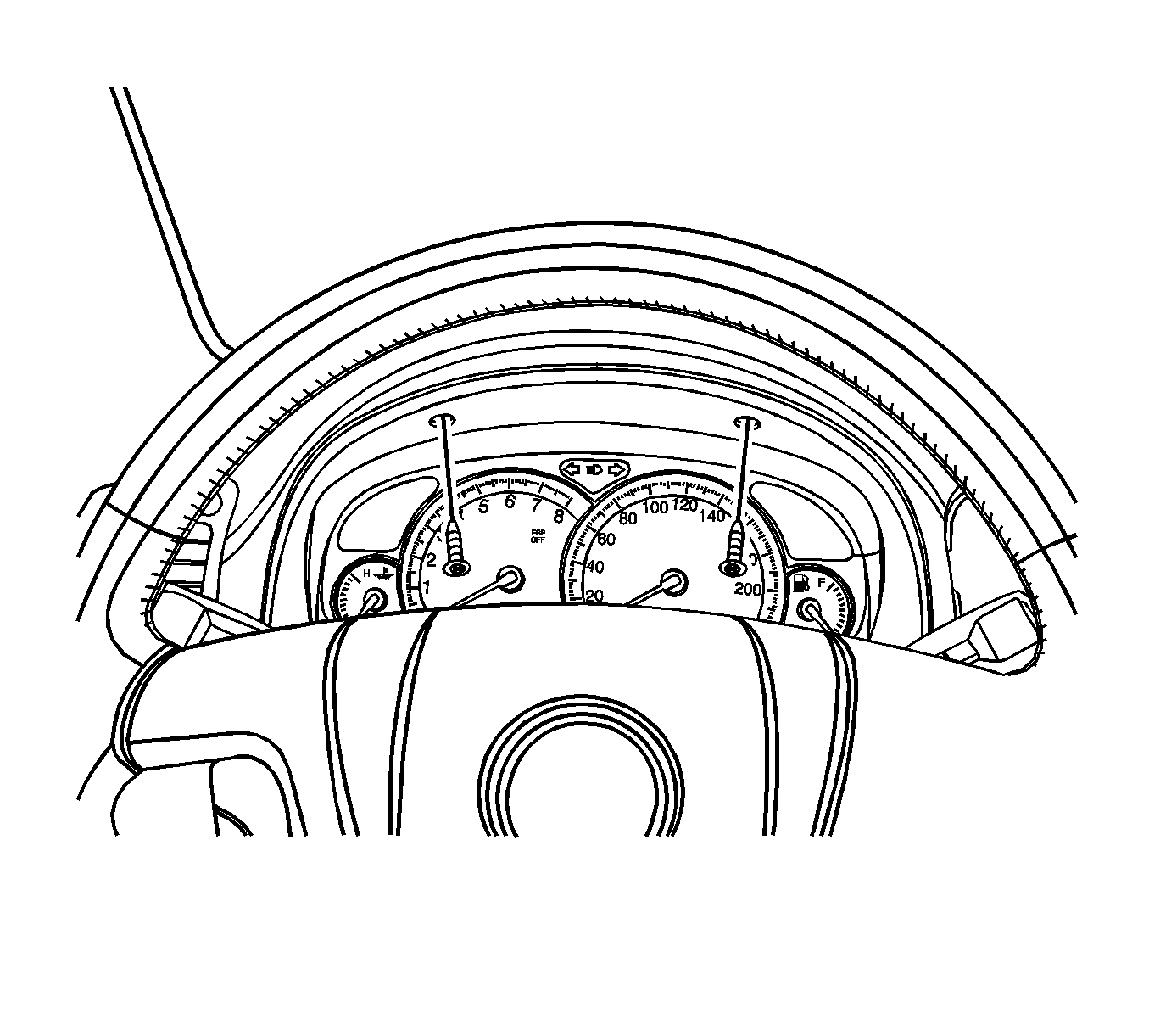
- Remove the instrument cluster. Refer to Instrument Cluster Replacement .
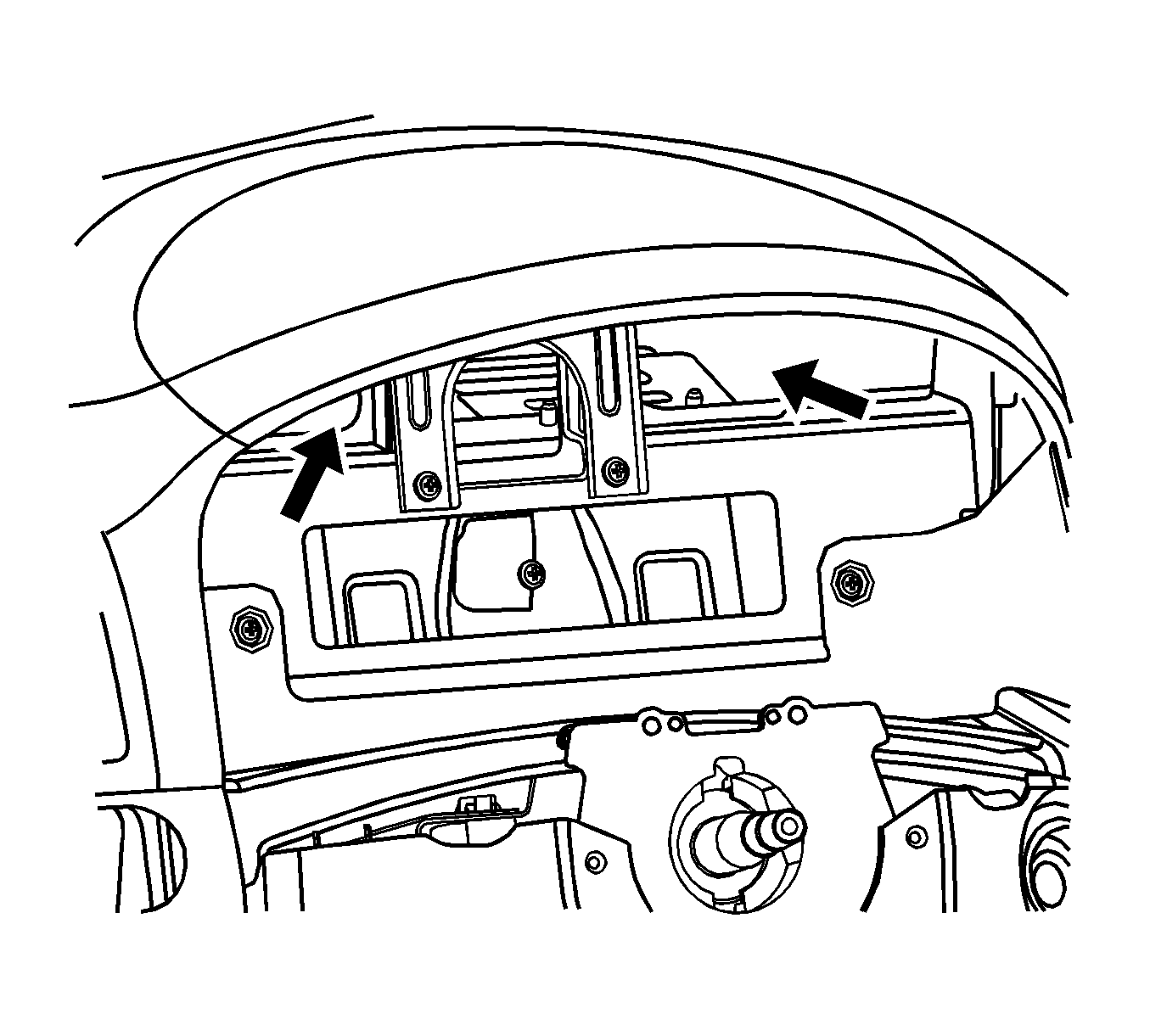
- Access the X-BCM on either side of bracket hole.
- Unlock both sides of X-BCM and remove the two nuts through the hole.
- Pull out the bracket through the hole.
- Disconnect the electrical connector.
- Pull out the X-BCM through the hole.
Caution: Refer to Battery Disconnect Caution in the Preface section.
Important: The left-hand drive is shown. The right-hand drive is similar.
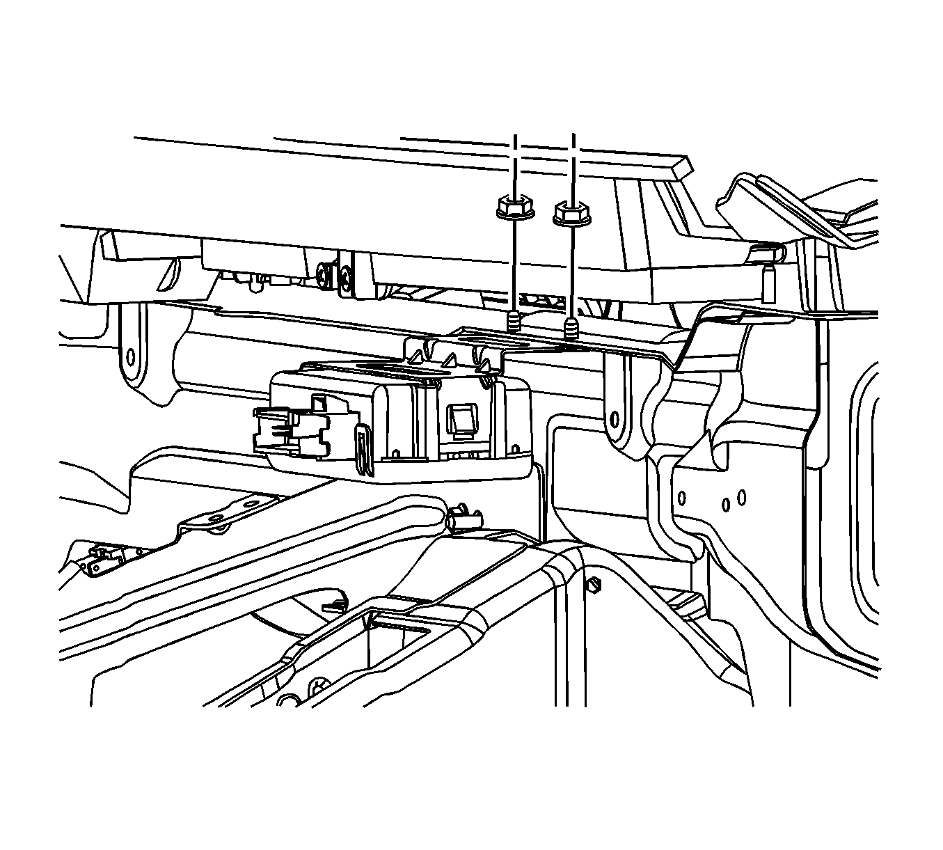
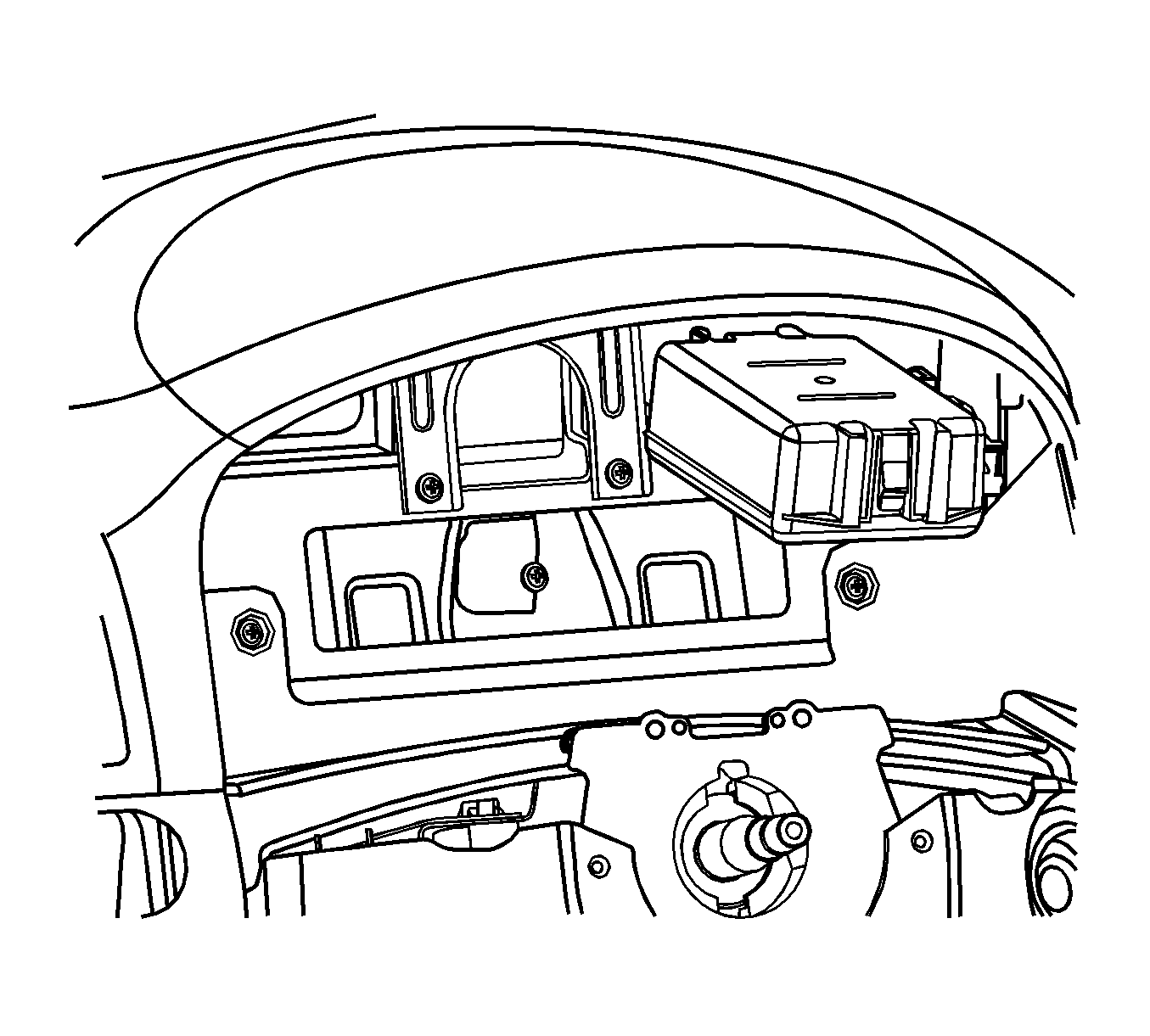
Important: Perform the SPO reprogramming when X-BCM module is replaced.
Installation Procedure
- Connect the electrical connector.
- Install the X-BCM and bracket with the nuts into the hole.
- Install the instrument cluster. Refer to Instrument Cluster Replacement .
- Connect the negative battery cable.


Body Control Module Replacement X-BCM C105/Short Body
Removal Procedure
- Disconnect the negative battery cable.
- Remove the instrument cluster. Refer to Instrument Cluster Replacement .
- Access the X-BCM on either side of bracket hole.
- Unlock both sides of X-BCM and remove the two nuts through the hole.
- Pull out the bracket through the hole.
- Disconnect the electrical connector.
- Pull out the X-BCM through the hole.
Caution: Refer to Battery Disconnect Caution in the Preface section.
Important: The left-hand drive is shown. The right-hand drive is similar.
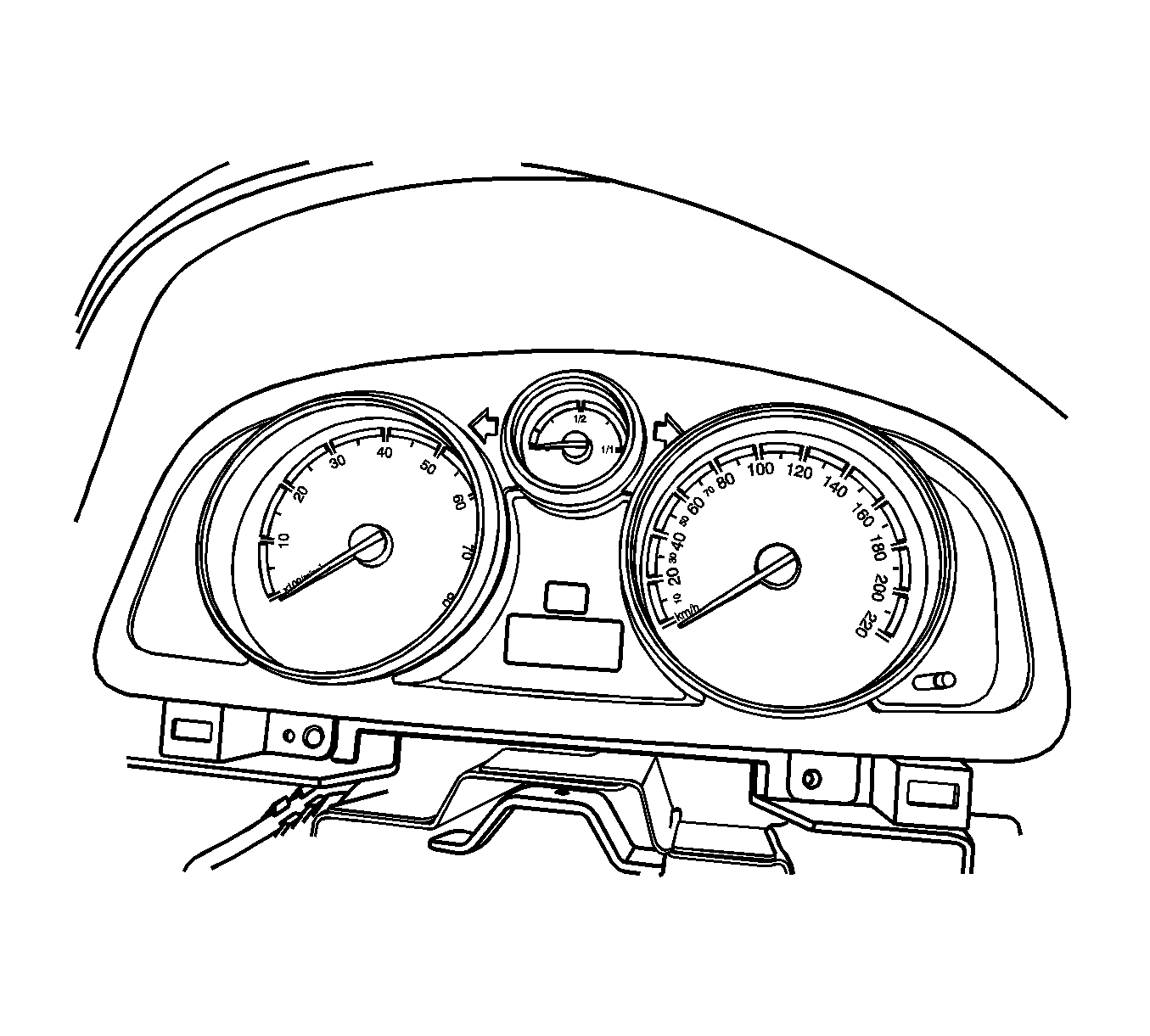


Important: Perform the SPO reprogramming when X-BCM module is replaced.
Installation Procedure
- Connect the electrical connector.
- Install the X-BCM and bracket with the nuts into the hole.
- Install the instrument cluster. Refer to Instrument Cluster Replacement .
- Connect the negative battery cable.


