Tools Required
KM-507-C Ball Joint Remover
Removal Procedure
- Raise and support the vehicle. Refer to Lifting and Jacking the Vehicle .
- Remove the front wheels. Refer to Tire and Wheel Removal and Installation .
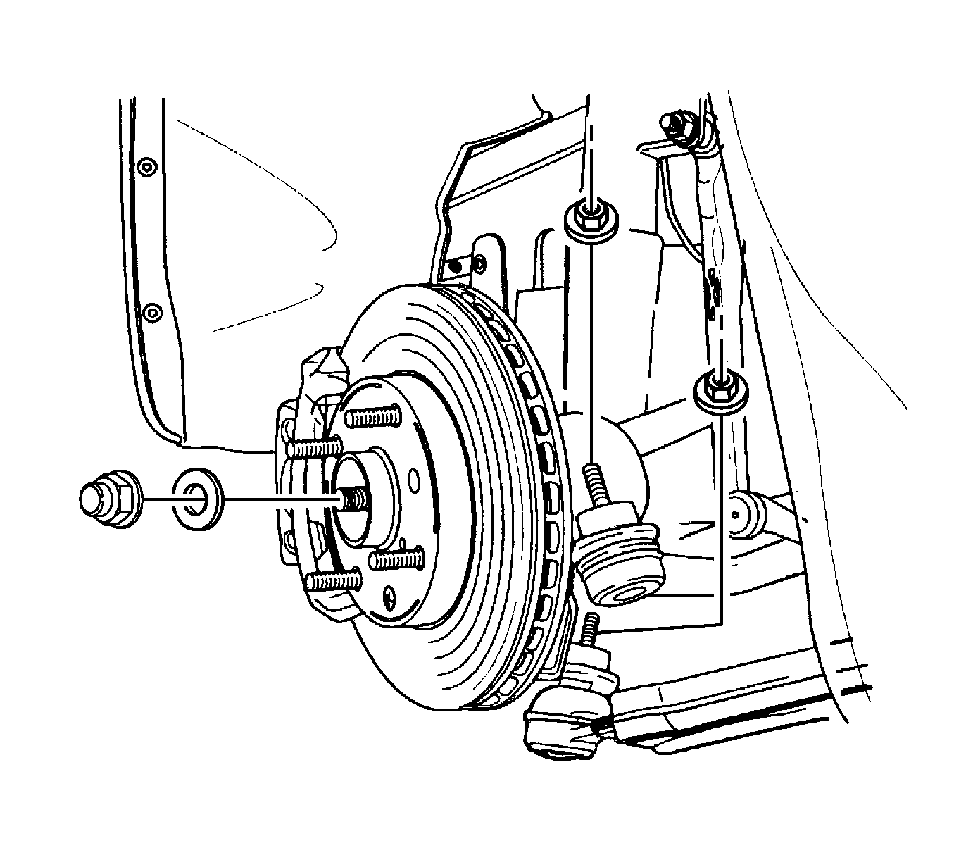
- Remove the axle shaft caulking nut. Discard the nut.
- Remove the lower ball joint nut.
- Use the KM-507-C in order to separate the lower ball joint from the steering knuckle.
- Remove the outer tie rod nut.
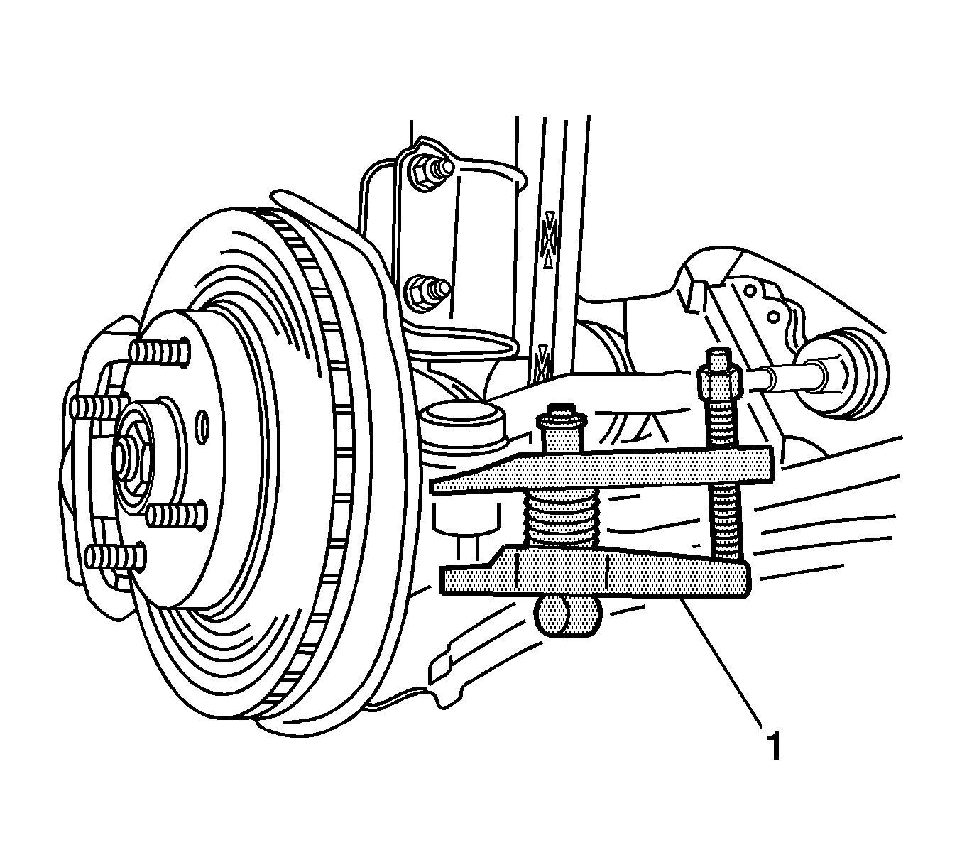
- Use the KM-507-C (1) in order to separate the outer tie rod end from the steering knuckle.
- Remove the brake caliper and the pads as an assembly and support the assembly with heavy mechanics wire, or equivalent. Verify there is no tension on the brake hose. Refer to Brake Caliper Replacement .
- Remove the brake rotor. Refer to Brake Rotor Replacement .
- Remove the ABS wheel speed sensor, if equipped. Refer to Front Wheel Speed Sensor Replacement .
- Remove the front strut nuts and bolts.
- Support the wheel drive shaft.
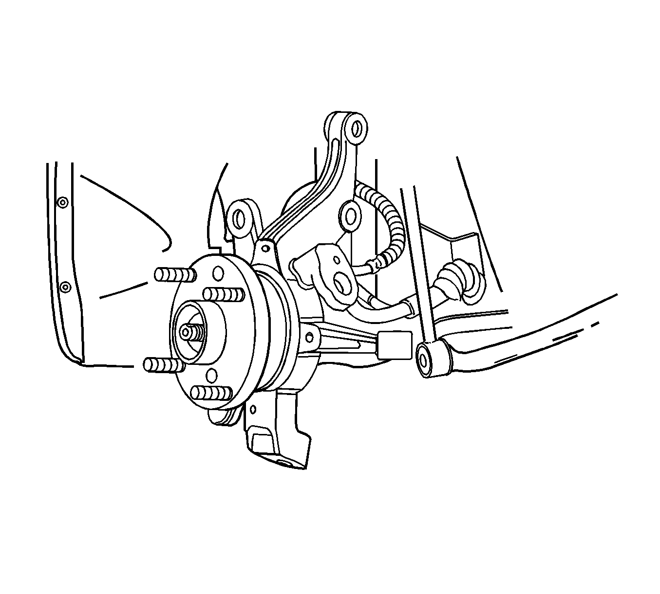
- Remove the knuckle assembly.
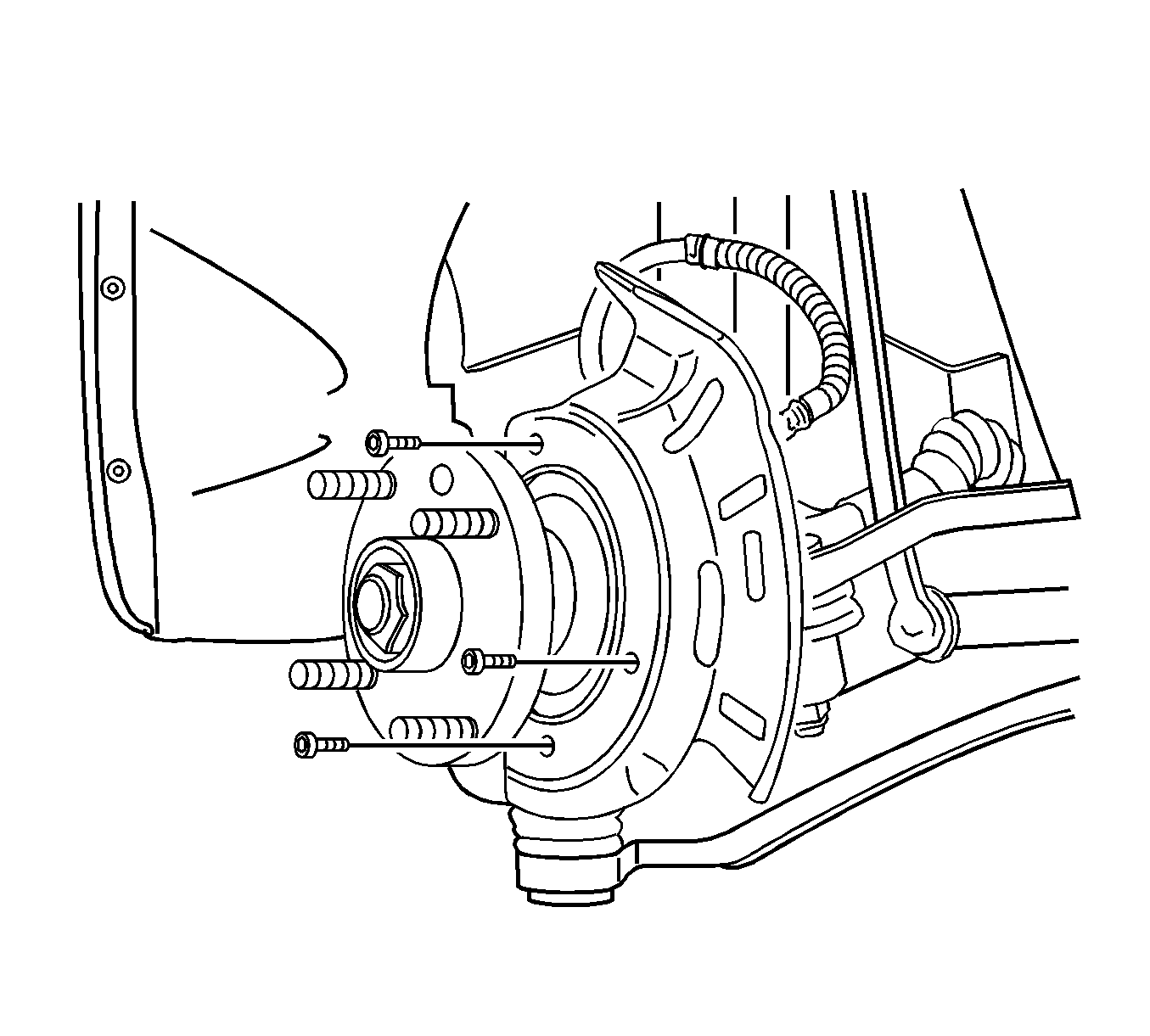
- Remove the wheel hub, bearing and seal from the knuckle. Refer to Wheel Hub, Bearing, Knuckle, and Seal Replacement .
- Remove the splash shield and the screws from the knuckle.
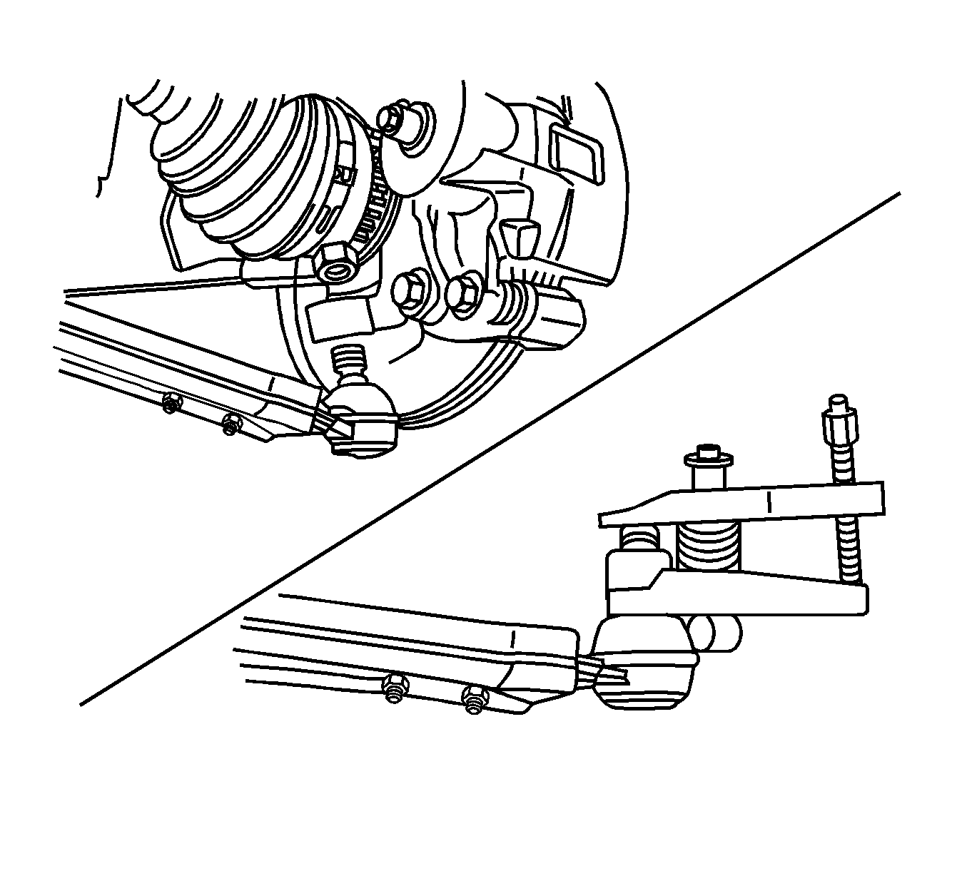
Notice: Use only the recommended tools for separating the ball joint from the knuckle. Failure to use the recommended tools may cause damage to the ball joint and seal.
Notice: Support the brake caliper with heavy mechanic wire, or equivalent, whenever it is separated from its mount and the hydraulic flexible brake hose is still connected. Failure to support the caliper in this manner will cause the flexible brake hose to bear the weight of the caliper, which may cause damage to the brake hose and in turn may cause a brake fluid leak.
Important: DO NOT disconnect the hydraulic brake flexible hose from the caliper.
Notice: Do not overextend the wheel drive shaft. Allowing the inboard joint to overextend can cause separation of the internal components and lead to joint failure.
Installation Procedure
- Install the splash shield to the knuckle with the screws.
- Install the wheel hub, bearing and seal to the knuckle. Refer to Wheel Hub, Bearing, Knuckle, and Seal Replacement .
- Install the knuckle assembly to the front strut with the nuts and bolts.
- Install the ABS wheel speed sensor. Refer to Front Wheel Speed Sensor Replacement .
- Install the brake rotor. Refer to Brake Rotor Replacement .
- Install the brake caliper. Refer to Brake Caliper Replacement .
- Install the lower ball joint to the steering knuckle.
- Install the lower ball joint nut.
- Install the outer tie rod end to the steering knuckle.
- Install the outer tie rod nut.
- Loosely install a NEW axle shaft caulking nut.
- Tighten the axle shaft caulking nut.
- Stake the caulking nut.
- Install the front wheels. Refer to Tire and Wheel Removal and Installation .
- Lower the vehicle.
- Inspect the vehicle. Refer to Preliminary Alignment Inspection and to Straight Ahead Inspection .
- Measure the wheel alignment.
- If necessary, adjust the front toe. Refer to Front Toe Adjustment .
Notice: Refer to Fastener Notice in the Preface section.
Tighten
Tighten the splash shield-to-steering knuckle screws to 4 N·m (35 lb in).
Tighten
Tighten the knuckle assembly to the front strut with nuts and bolts to 100 N·m (74 lb ft).
Tighten
Tighten the lower ball joint nut to 55 N·m (41 lb ft).
Tighten
Tighten the outer tie rod nut to 45 N·m (33 lb ft).
Tighten
Tighten the axle shaft caulking nut to 300 N·m (221 lb ft).
