EVAP Canister Purge System Inspection
Caution: Do not breathe the air through the EVAP component tubes or hoses. The fuel vapors inside the EVAP components may cause personal injury.
Important: Perform a careful visual inspection of the EVAP control system components and connecting hoses before the diagnosis of an EVAP control system malfunction.
- Allow the engine to cool to room temperature.
- Start the engine (cold).
- Disconnect the purge hose from the EVAP canister.
- Place a finger against the end of the disconnected hose and check for vacuum. Vacuum should not be felt when the engine is below normal operating temperatures.
- Connect the purge hose to the EVAP canister and warm the engine up to normal operating temperature.
- Disconnect the purge hose from the EVAP canister.
- Place a finger over the disconnected hose and check for vacuum. Vacuum should be felt with the engine running at normal operating temperature.
Important: The EVAP control system does not perform EVAP canister purging (vacuum is not detected at the purge hose) unless the engine is sufficiently warmed up and the heated oxygen sensor (HO2S) is fully activated. When the purge hose is disconnected as in step 6, some air may be drawn into the purge line. As a result, the powertrain control module (PCM) might detect a change in the purge gas concentration and stop purging. This is a normal action and may be the cause of a failure to detect vacuum in step 7. If no vacuum is felt in step 7, continued testing of the EVAP system may be necessary in order to avoid the replacement of good parts.
Failure of the EVAP control system to pass any of these checks indicates a possible malfunction that will require further inspection.EVAP Canister Inspection
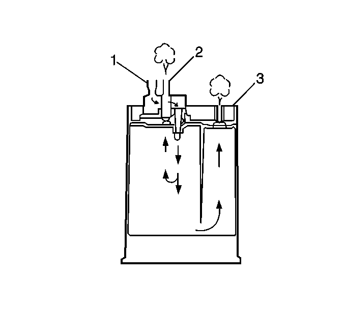
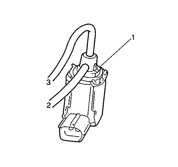
- Disconnect the vacuum hoses from the EVAP canister.
- Blow air into the tank pipe (1) of the EVAP canister. There should be no restriction of air flow through the purge pipe (2) and the air pipe (3).
- Replace the EVAP canister if the EVAP canister fails the above check. Refer to Evaporative Emission Canister Replacement.
- Connect the vacuum hoses to the EVAP canister.
EVAP Canister Purge Valve Inspection
Tools Required
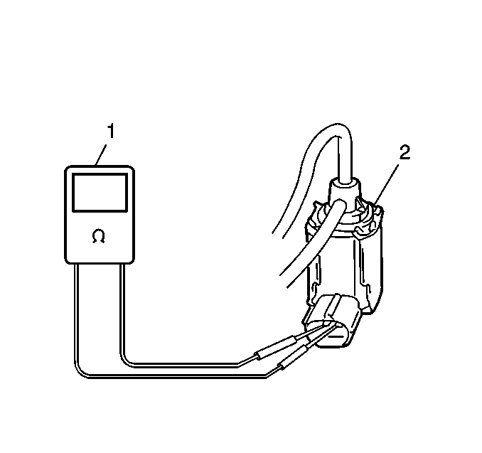
J 39200 Digital Multimeter
- Disconnect the EVAP canister purge valve electrical connector.
- Measure the resistance between the electrical terminals of the EVAP canister purge valve (2) with the DMM (1). The resistance should be 28 to 39 ohms at 20°C (68°F).
- Replace the EVAP canister purge valve if the resistance is not 28 to 39 ohms at 20°C (68°F). Proceed to step 4 if the resistance is within the specification. Refer to Evaporative Emission Canister Purge Solenoid Valve Replacement.
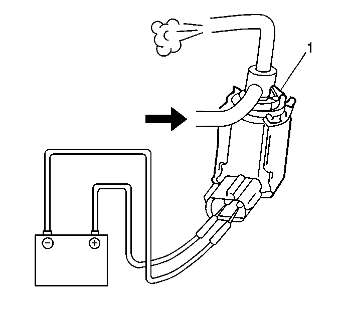
- Disconnect the EVAP canister purge valve vacuum hose (3) from the intake manifold.
- Disconnect the EVAP canister purge valve vacuum hose (2) from EVAP canister.
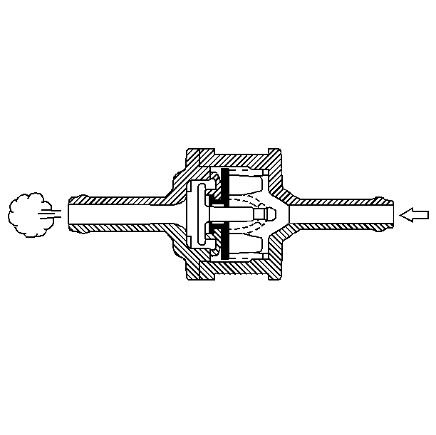
- Blow air into the EVAP canister purge valve vacuum hose (2) that was disconnected from the EVAP canister. Air should not pass through the EVAP canister purge valve (1) and exit from the intake manifold hose (3).
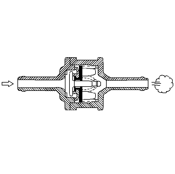
- Connect 12 volts DC to the EVAP canister purge valve electrical terminals.
- Blow air into the EVAP canister purge valve vacuum hose that was disconnected from the EVAP canister. Air should pass through the EVAP canister purge valve and exit from the intake manifold hose.
- Replace the EVAP canister purge valve if the EVAP canister purge valve failed this inspection. Refer to Evaporative Emission Canister Purge Solenoid Valve Replacement.
- Connect the EVAP canister purge valve vacuum hoses.
- Connect the EVAP canister purge valve electrical connector.
Fuel Tank Pressure Control Valve Inspection
Tools Required
J 23738-A Hand Vacuum Pump
- Connect a hose to the fuel tank side of the pressure control valve on the fuel tank.
- Blow hard into the hose. Some air should pass through the valve from the fuel tank side to the canister side when blown hard.
- Remove the hose from the fuel tank side, and connect the hose to the canister side of the pressure control valve.
- Blow easily into the hose. Even lightly blown air should pass smoothly through the valve from the canister side to the fuel tank side.
- Replace the pressure control valve if the valve fails any of the above checks. Refer to Fuel Tank Pressure Control Valve Replacement .