Coil Spring Replacement With Independent Rear Suspension
Tools Required
J 41820 Ball Joint/Stud Separator
Removal Procedure
- Raise and support the vehicle. Refer to Lifting and Jacking the Vehicle .
- Remove the rear wheel. Refer to Tire and Wheel Removal and Installation .
- Inspect the rear ball joints. Refer to Ball Joint Inspection .
- Remove the brake caliper and support the brake caliper. Do not disconnect the brake hose. Refer to Rear Brake Caliper Replacement .
- Disconnect the tie rod from the knuckle. Refer to Tie Rod Replacement .
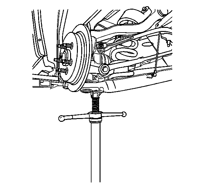
- Use a utility stand in order to support the lower control arm.
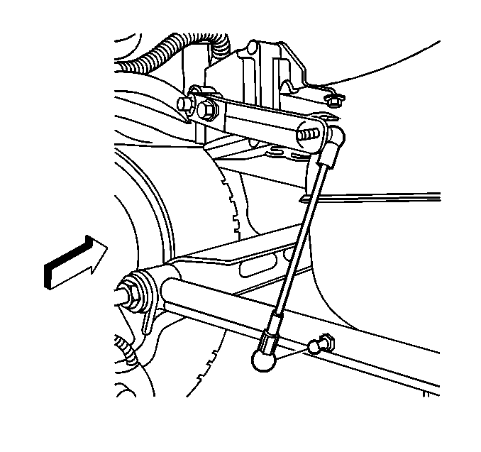
- Disconnect the height sensor link from the lower control arm.
- Disconnect the shock absorber from the lower control arm. Refer to Shock Absorber Replacement .
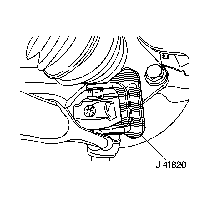
- Use the J 41820 in order to disconnect the ball joint from the knuckle.
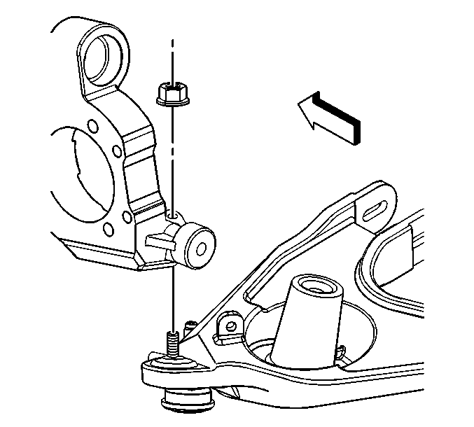
- Remove the lower ball joint nut.
- Use the utility stand in order to lower the control arm and relieve the coil spring tension.
- Carefully remove the coil spring and jounce bumper .
- Remove the spring insulator (2).
- Remove the lower control arm.
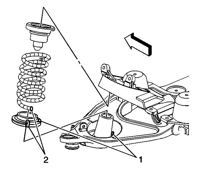
Notice: Care should be taken to avoid chipping or scratching the spring coating when handling the rear suspension coil spring. Damage to the coating can cause premature failure.
Installation Procedure
- Install the spring jounce bumper to the spring.
- Index and install the spring insulator to the spring (2).
- Index and install the spring insulator with the spring and the jounce bumper to the lower control arm (1).
- Use the utility stand in order to raise the lower control arm.
- Install the lower ball joint to the knuckle.
- Install the lower ball joint nut.
- Connect the shock absorber to the lower control arm. Refer to Shock Absorber Replacement .
- Connect the height sensor link to the lower control arm.
- Connect the tie rod to the knuckle. Refer to Tie Rod Replacement .
- Install the brake caliper. Refer to Rear Brake Caliper Replacement .
- Install the rear wheel. Refer to Tire and Wheel Removal and Installation .
- Raise and support the vehicle. Refer to Lifting and Jacking the Vehicle .


Notice: Refer to Fastener Notice in the Preface section.
Tighten
Tighten the ball joint nut to 35 N·m (26 lb ft) plus 130 degrees.

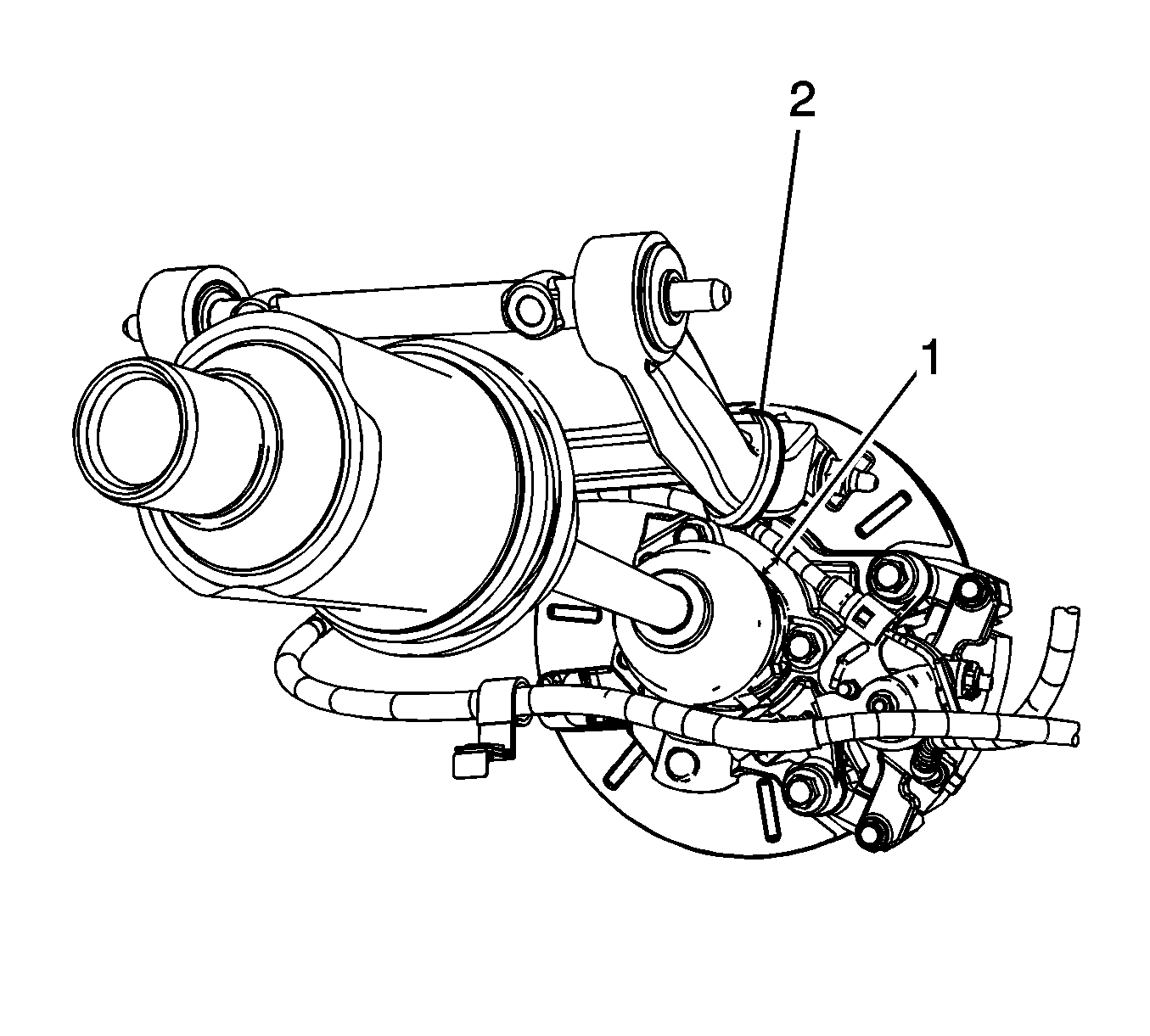
Important: Maintain proper rear park brake cable routing and clearances. Verify the rear park brake cables have a minimum of 10 mm and a maximum of 12 mm of clearance to the wheel drive shafts (1). Maintain this clearance using retention straps or equivalent retention (2).
Coil Spring Replacement All Wheel Drive
Tools Required
J 41820 Ball Joint/Stud Separator
Removal Procedure
- Raise and support the vehicle. Refer to Lifting and Jacking the Vehicle .
- Remove the rear wheel. Refer to Tire and Wheel Removal and Installation .
- Inspect the rear ball joints. Refer to Ball Joint Inspection .
- Remove the brake caliper and support the brake caliper. Do not disconnect the brake hose. Refer to Rear Brake Caliper Replacement .
- Disconnect the tie rod from the knuckle. Refer to Tie Rod Replacement .
- Use a utility stand in order to support the lower control arm.
- Disconnect the height sensor link from the lower control arm.
- Disconnect the shock absorber from the lower control arm. Refer to Shock Absorber Replacement .
- Use the J 41820 in order to disconnect the ball joint from the knuckle.
- Remove the lower ball joint nut.
- Use the utility stand in order to lower the control arm and relieve the coil spring tension.
- Carefully remove the coil spring and jounce bumper .
- Remove the spring insulator (2).
- Remove the lower control arm.


Notice: Care should be taken to avoid chipping or scratching the spring coating when handling the rear suspension coil spring. Damage to the coating can cause premature failure.
Installation Procedure
- Install the spring jounce bumper to the spring.
- Index and install the spring insulator to the spring (2).
- Index and install the spring insulator with the spring and the jounce bumper to the lower control arm (1).
- Use the utility stand in order to raise the lower control arm.
- Install the lower ball joint to the knuckle.
- Install the lower ball joint nut.
- Connect the shock absorber to the lower control arm. Refer to Shock Absorber Replacement .
- Connect the height sensor link to the lower control arm.
- Connect the tie rod to the knuckle. Refer to Tie Rod Replacement .
- Install the brake caliper. Refer to Rear Brake Caliper Replacement .
- Install the rear wheel. Refer to Tire and Wheel Removal and Installation .
- Raise and support the vehicle. Refer to Lifting and Jacking the Vehicle .


Notice: Refer to Fastener Notice in the Preface section.
Tighten
Tighten the ball joint nut to 35 N·m (26 lb ft) plus 130 degrees.


Important: Maintain proper rear park brake cable routing and clearances. Verify the rear park brake cables have a minimum of 10 mm and a maximum of 12 mm of clearance to the wheel drive shafts (1). Maintain this clearance using retention straps or equivalent retention (2).
Coil Spring Replacement Front Wheel Drive with Axle
Removal Procedure
Caution: When removing the rear springs, do not use a twin-post type hoist. The swing arch tendency of the rear axle assembly when certain fasteners are removed may cause it to slip from the hoist which may cause personal injury.
- Raise and support the vehicle. Refer to Lifting and Jacking the Vehicle .
- Remove the brake hose bracket screw from the control arm. Refer to Rear Brake Hose Replacement .
- Use the utility stand in order to support the center of the rear axle.
- Remove the shock absorber lower bolts and nuts. Refer to Shock Absorber Replacement .
- Remove the rear axle tie rod from the rear axle. Refer to Tie Rod Replacement .
- Use the utility stand in order to lower the rear axle.
- Remove the springs (4), the insulators (3, 5), spring seats (2), and jounce bumpers (1).
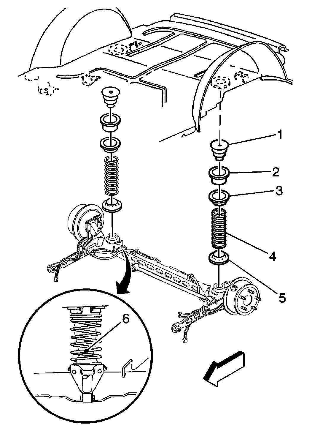
Notice: Do not suspend the rear axle by the brake hoses. Damage to the brake hoses may result.
Notice: Care should be taken to avoid chipping or scratching the spring coating when handling the rear suspension coil spring. Damage to the coating can cause premature failure.
Installation Procedure
- Install the jounce bumpers (1), spring seats (2), springs (4), the insulators (3, 5).
- Index mark (6) on springs to axle.
- Use the utility stand in order to raise the rear axle.
- Install the rear axle tie rod to the rear axle. Refer to Tie Rod Replacement .
- Install the shock absorbers to the rear axle. Refer to Shock Absorber Replacement .
- Install the brake hose bracket to the control arm. Refer to Rear Brake Hose Replacement .
- Remove the utility stand.
- Lower the vehicle.

Notice: Care should be taken to avoid chipping or scratching the spring coating when handling the rear suspension coil spring. Damage to the coating can cause premature failure.
Important: Position the spring so that the paint stripe (6) is facing rearward and centered to the shock absorber.
