For 1990-2009 cars only
Removal Procedure
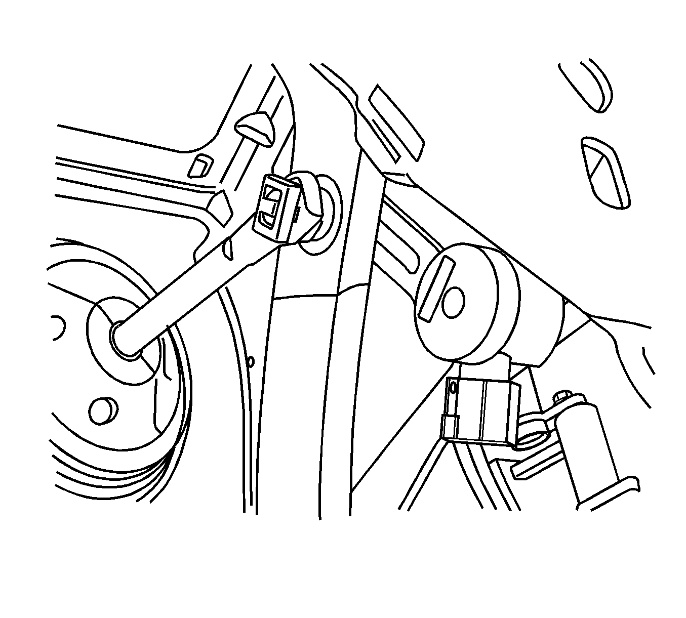
- Remove the instrument panel (I/P) insulator. Refer to Knee Bolster, Insulator, Molding Replacement - Instrument Panel in Instrument Panel, Gages, and Console.
- Disengage but do not remove the connector position assurance (CPA) on the connector.
- Remove the screw.
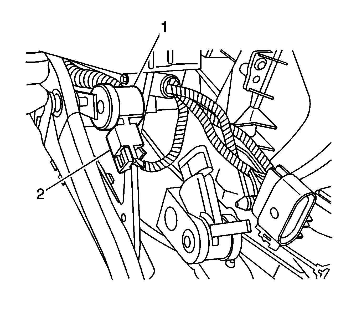
- Remove the brake pedal position sensor.

Disconnect the electrical connector (2).

Installation Procedure
- Apply adhesive GM P/N 12345493 (Canadian P/N 10953488) to the screw.
- Position the sensor fork to the pin.
- Rotate the sensor in order to align the sensor locator to the hole in the extension bracket.
- Install the brake pedal position sensor screw.
- Connect the electrical connector (2).
- Calibrate the sensor. Refer to Brake Pedal Position Sensor Calibration .
- Install the I/P insulator. Refer to Knee Bolster, Insulator, Molding Replacement - Instrument Panel in Instrument Panel, Gages, and Console.

Notice: Refer to Fastener Notice in the Preface section.
Tighten
Tighten the screw to 2 N·m (18 lb in).

Engage the CPA. The CPA will not engage if the connector is not attached properly.
