DTC P0502 Vehicle Speed Sensor (VSS) Circuit Low Input Manual Trans Only
Circuit Description
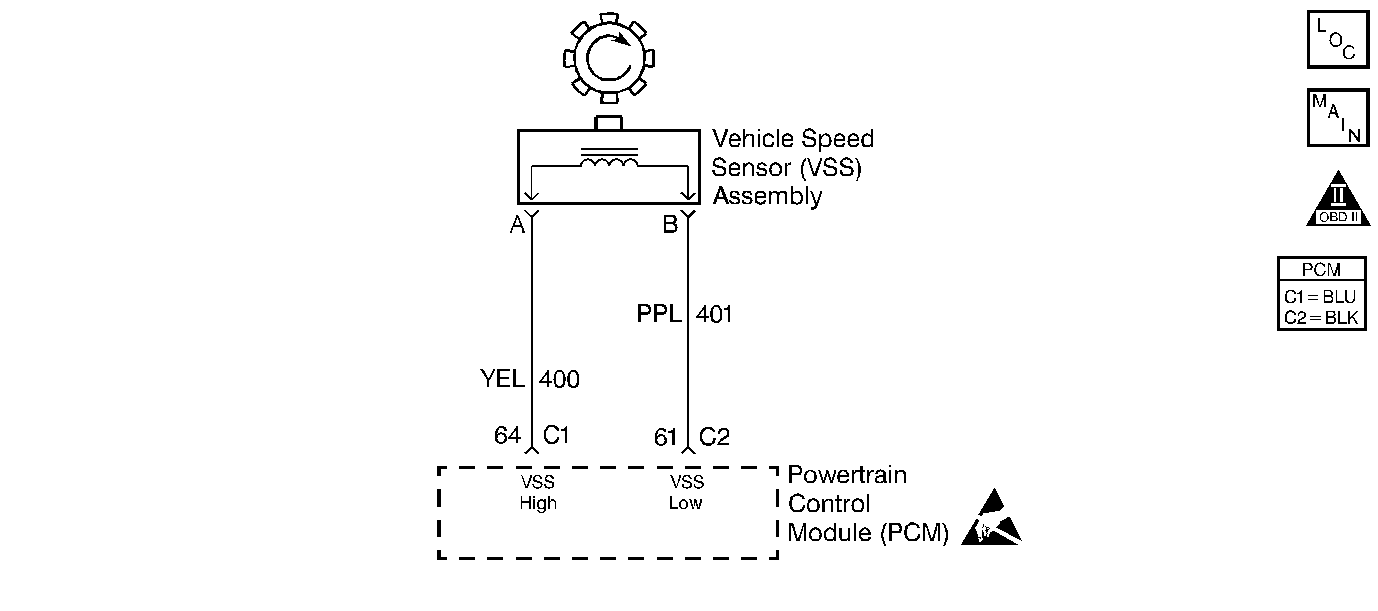
Vehicle speed information is provided to the Powertrain Control Module (PCM) by the vehicle speed sensor (VSS). The VSS is a permanent magnet generator that is mounted in the transaxle and produces a pulsing voltage whenever vehicle speed is over about 3 mph (5 km/h). The AC voltage level and the number of pulses increases with vehicle speed. The PCM converts the pulsing voltage into km/h (mph) and then supplies the necessary signal to the instrument panel for speedometer, odometer operation and to the cruise control module and multi-function alarm module operation.
Conditions for Setting the DTC
| • | Vehicle speed is less than 2 mph (3 km/h). |
| • | Engine speed is between 1700 and 3600 RPM. |
| • | Throttle Position (TP) is between 0-1%. |
| • | Engine vacuum is between 80-70 kPa. |
| • | Above conditions met for 5 seconds. |
| • | DTCs P0107, P0108, P0122, and P0123 not set. |
Action Taken When the DTC Sets
| • | The malfunction indicator lamp (MIL) illuminates. |
| • | The PCM records the operating conditions at the time when the diagnostic fails. This information stores in the Freeze Frame and Failure Records buffers. |
| • | A history DTC stores. |
| • | The coolant fan turns ON. |
Conditions for Clearing the MIL/DTC
| • | The MIL will turn OFF after three consecutive ignition cycles in which the diagnostic runs without a fault. |
| • | A history DTC will clear after 40 consecutive warm-up cycles without a fault. |
| • | The MIL/DTCs can be cleared by using the scan tool. |
Diagnostic Aids
| • | An Intermittent problem may be caused by a poor connection, rubbed through wire insulation, or a wire that is broken inside the insulation. |
| • | VSS high and low CKT(s) should be thoroughly checked for the following conditions: |
| - | Backed out terminals |
| - | Improper mating |
| - | Broken locks |
| - | Improperly formed |
| - | Damaged terminals |
| - | Poor terminal to wiring connections |
| - | Physical damage to the wiring harness or for proper routing |
| • | Ensure the VSS is correctly torqued to the transmission housing. |
| • | Refer to Symptoms . |
Test Description
Numbers below refer to the step numbers on the Diagnostic Table.
-
The Powertrain OBD System Check prompts the technician to complete some basic checks and store the freeze frame and failure records data on the scan tool if applicable. This creates an electronic copy of the data taken when the malfunction occurred. The information is then stored on the scan tool for later reference.
-
The permanent magnet generator only produces a signal if the drive wheels are turning greater than 3 mph (5 km/h). This step determines if DTC P0502 is the result of a hard malfunction or an intermittent condition.
-
Proper engine loads cannot be achieved in a shop environment to properly run the vehicle within the Freeze Frame Data conditions. It will be necessary to drive the vehicle on the road to obtain the proper engine loads.
-
This step verifies that the PCM is receiving a signal from the vehicle speed sensor.
-
Refer to service bulletin information for the latest calibration update.
-
Refer to the latest Techline information for programming procedures.
-
A resistance reading that is higher than the specified value indicates that the VSS circuitry is open.
-
If the displayed resistance were less than the 1,300 ohms, the VSS high and low circuits are shorted together. If the resistance value within the specified value, check the VSS high and low circuits for a short to ground.
-
This checks the resistance of the VSS if no opens or shorts were found on the VSS high and low circuits.
-
The replacement PCM must be programmed and the crankshaft position system variation procedure must be preformed. Refer to the latest Techline procedures for PCM reprogramming and Crankshaft Position System Variation Learn .
Step | Action | Value(s) | Yes | No | ||||
|---|---|---|---|---|---|---|---|---|
Was the Powertrain On-Board Diagnostic (OBD) System Check performed? | -- | Go to Powertrain On Board Diagnostic (OBD) System Check 2.4L or | ||||||
Notice: In order to avoid damage to the drive axles, support the lower control arms in the normal horizontal position. Do not run the vehicle in gear with the wheels hanging down at full travel. Does the scan tool display vehicle speed above the specified value? | 0 MPH | |||||||
Does the scan tool display the vehicle speed above the specified value? | 0 MPH | |||||||
Is the AC voltage greater than or equal to the specified value? | 0.5V | |||||||
Check for the most current calibration ID number. Is the latest calibration ID in the vehicle? | -- | |||||||
Update the PCM with the latest calibration ID. Is the action complete? | -- | -- | ||||||
7 | Measure the resistance with a DMM at the PCM electrical connector terminals between the following circuits:
Is the resistance greater than the specified value? | 870ohms | ||||||
Was a repair necessary? | -- | |||||||
9 | Was the resistance value within or equal to the specified value? | 530-870ohms | ||||||
Was a repair necessary? | -- | |||||||
Is the resistance value within the specified value? | 530-870ohms | |||||||
12 | Replace the Vehicle Speed Sensor (VSS). Refer to Vehicle Speed Sensor in Manual Transmission. Is the action complete? | -- | -- | |||||
Replace the PCM. Refer to Powertrain Control Module Replacement . Is the action complete? | -- | -- | ||||||
14 |
Does the scan tool indicate that this diagnostic has ran and passed? | -- | ||||||
15 | Check if any additional DTCs are set. Are any DTCs displayed that have not been diagnosed? | -- | Go to applicable DTC table | System OK |
