A/C SYSTEM CONTAMINATED COMPRESSOR REPLACE PROCEDURE

VEHICLES AFFECTED: 1977-1986 - All Models
Some air conditioning system components including the refrigerant oil may become contaminated as a result of air conditioning compressor failure. Contaminated oil or debris in the air conditioning system may inhibit proper oil circulation and result in a repeat compressor failure. Refrigerant oil and other debris can be removed from air conditioning system components by flushing with refrigerant 11 (R-11). The procedure described in this bulletin is to be followed whenever an air conditioning compressor is replaced.
Proper flushing with R-11 will ensure that maximum performance will be obtained and reduce the possibility of a repeat compressor failure. R-11 is effective in removing refrigerant oil, metal particles and other debris from air conditioning refrigerant components. R-11 packaged in a 30 pound canister pressurized with nitrogen to 40 psi, is recommended for this process.
The presence of debris in air conditioning systems equipped with an expansion (orifice) tube can readily be determined by inspecting the expansion tube. Some components, because of their design, tend to trap particles. These components (listed later in this bulletin) must be replaced if debris is inside the component. Flushing with R-11 must be performed as described in the bulletin. Past service information manual air conditioning flushing procedures using refrigerant 12 (R-12), repetitive cleaning of expansion (orifice) tube or not allowing R-11 to soak a minimum of five minutes are not acceptable and must be superseded by this bulletin. Although R-11 does not adversely affect air conditioning performance when used as directed, misuse of the product or not properly following service information manual procedures on adjusting refrigerant oil quantities may result in compressor damage or poor performance.
Air conditioning refrigerant system flushing is required whenever:
1. A compressor has failed resulting in debris in the air conditioning system refrigerant components or oil.
2. Inspection of the orifice tube shows the inlet screen to be 25% or more coated with debris.
3. Refrigerant oil is overcharged or contaminated.
Proper flushing of an air conditioning system can only be achieved by flushing each component separately and allowing the R-11 to soak in each component a minimum of five minutes. Before recharging and operating the air conditioning system, all of the R-11 must be removed and the proper amount of 525 viscosity refrigerant oil added. Flushing a complete air conditioning system requires approximately 15 pounds of R-11, four pounds of R-12 and up to 11 ounces of 525 viscosity refrigerant oil. The actual quantities of R-11, R-12 and oil depends on the system, the number of components flushed and the amount of debris in each component. R-11 is removed by purging the component with R-12 followed by system evacuation.
Air Conditioning System Flushing Procedure
When required, use the following procedure to properly flush the air conditioning refrigerant system.
1. Discharge the air conditioning refrigerant system -
Discharge the system following the discharging, adding oil, evacuating and charging procedures as outlined in the appropriate service Information Manual.
2. Disassemble the air conditioning system -
Disconnect and remove from the vehicle the air conditioning compressor, accumulator and all air conditioning refrigerant lines and hoses. Keep the accumulator capped when not flushing. Remove and discard all O-rings.
3. Inspect the air conditioning refrigerant system for debris -
A. Remove the expansion (orifice) tube from the evaporator inlet (or liquid line) by gripping the plastic tip with a needle nose pliers, tool J-26549-D or equivalent. Inspect the expansion tube screens. if either screen is intact, debris should have been prevented from entering the evaporator and accumulator. If both screens are damaged, the expansion tube must be replaced and harmful debris has probably entered the evaporator and accumulator. If the expansion tube is heavily coated with debris, replace the expansion tube and inspect the compressor for internal damage. Replace the compressor as required.
B. Inspect the condenser, evaporator, discharge hose and accumulator for debris. The design of some air conditioning components is such that flushing will not remove debris other than fine brass. Flushing these components will remove refrigerant oil and fine brass only. The components listed below must be replaced if inspection reveals the presence of harmful debris.
a) Condenser - as evidenced by a plugged orifice tube screen.
b) Evaporator - as evidenced either by both orifice tube screens being damaged or actual debris in the component.
c) Discharge hose with baffled muffler - as evidenced by a plugged orifice tube screen.
d) Accumulator - as evidenced either by orifice tube screens being damaged or debris other than fine brass in the drained oil.
Also, replace the accumulator if the desiccant requires replacement. Please see accumulator assembly in the appropriate Service Information Manual for conditions requiring accumulator replacement.
4. Flush the air conditioning refrigerant system -
The air conditioning refrigerant system is comprised of the condenser, evaporator, discharge/suction hose set, accumulator, liquid lines and compressor. This procedure utilizes tool kit J-33883-A or equivalent, refrigerant 11 (R-11), refrigerant 12 (R-12) and extension tubes. Tool kit J-33883-A includes the following:
A. Small orifice nozzle flush gun J-33883-15 B. Large orifice nozzle flush gun J-33883-50 C. Yellow refrigerant charging hose J-5418-48Y D. R-11 reservoir cylinder E. Plastic storage box
The small orifice nozzle flush gun J-33883-15 is recommended for flushing small lines and hoses with R-11. The large orifice nozzle flush gun J-33883-50 is recommended for purging all components with R-12 and flushing large components with R-11 or where a large quantity of R-11 is desired. A 30 pound pressurized R-11 canister should be used for refrigerant system flushing. If non-pressurized liquid R-11 solvent is used, the reservoir cylinder from tool kit J-33883-A or equivalent must be filled with the liquid R-11 and pressurized with R-12. R-12 packaged in a 30 pound canister is recommended for purging R-11 from the air conditioning system. R-11 and R-12 should be dispensed as follows:
A. Liquid R-11 - connect the small orifice nozzle flush gun J-33883-15 or large nozzle flush gun J-33883-50 to the R-11 canister or reservoir cylinder (both in the upright position) using the yellow refrigerant charging hose J-5418-48Y. If an equivalent to P/N 12345074 is used, check its label for proper orientation to dispense liquid R-11.
B. Vapor R-12 - connect the large orifice nozzle flush gun J-33883-50 to the R-12 canister (upright position) using the yellow refrigerant charging hose.
The extension tubes can be made from scrap pieces of clean 3/8, 1/2 and 3/4 inch air conditioning lines and the appropriate size clean rubber hose (see figures 1 and 2). The rubber hoses must be long enough to drain into a suitable waste container.
CAUTION:
R-11 is the only approved solvent for flushing air conditioning systems. Extreme caution and adherence to all safety precautions governing the use of refrigerants are necessary when flushing the air conditioning system. Always work in a well ventilated area and avoid breathing any vapors. See handling refrigerant 12 inch procedures as outlined in the appropriate Service Information Manual.
It is important that all the R-11 is thoroughly removed from each component. Failure to remove all the R-11 from the refrigerant system may result in compressor damage and poor performance. The following guidelines will ensure the ability to thoroughly remove all R-11 from the various air conditioning system components:
a) Component temperature must be 24 deg. C (75 deg. F) minimum.
b) Use of heat lamps on metal components will help remove R-11 and will reduce the time required to evacuate the refrigerant system.
A. Flush condenser (on car) -
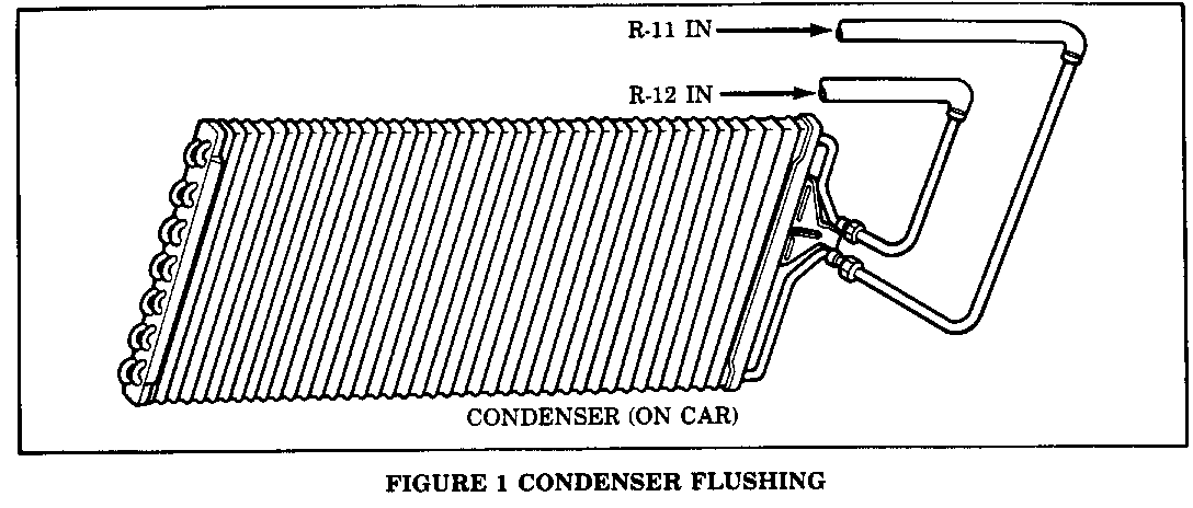
a) Attach extension tubes to the condenser bottom (outlet) and top (inlet) fittings, see figure 1. The tubes must extend above the condenser core and drain into a suitable waste container.
b) Force liquid R-11 into the condenser bottom (outlet) fitting extension tube until clean R-11 flows from the condenser top (inlet) fitting extension tube, see figure 1. Use the large orifice nozzle flush gun J-33883-50 or equivalent.
c) Cap the tubes with air conditioning hose end caps or appropriate plugs. Wait a minimum of 5 minutes before removing caps and draining the condenser.
d) Force R-12 vapor into the condenser top (inlet) fitting extension tube to purge the remaining R-11, see figure 1. Use the large orifice nozzle flush gun J-33883-50 or equivalent. Continue to blow R-12 vapor until no liquid is observed leaving the condenser bottom (outlet) fitting extension tube.
B. Flush evaporator (on car) -
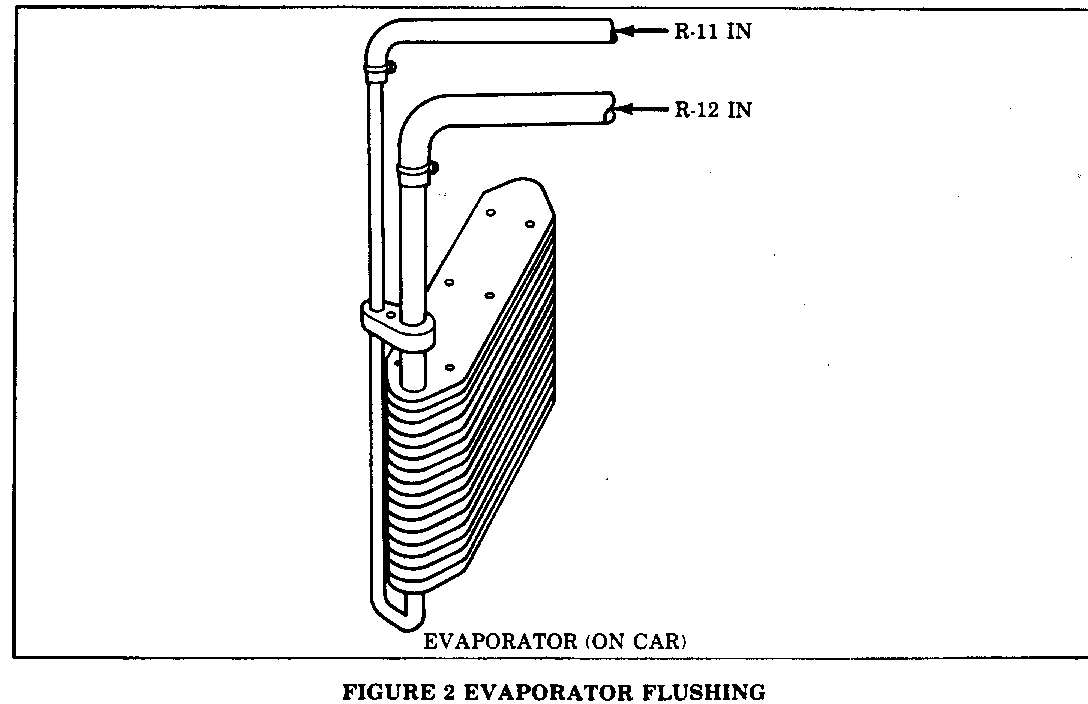
a) Attach extension tubes to the evaporator small opening (inlet) and large opening (outlet/suction side), see figure 2. Use the large orifice nozzle flush gun J-33883-50 or equivalent.
b) Cap the tubes with air conditioning hose end caps or appropriate plugs. Wait a minimum of 5 minutes before removing caps and draining the evaporator.
c) Force R-12 vapor into the vaporator large opening (outlet/suction side) extension tube to purge the remaining R-11, see figure 2. Use the large orifice nozzle flush gun J-33883-50 or equivalent. Continue to blow R-12 vapor until no liquid is observed leaving the evaporator small opening (inlet) extension tube.
It is mandatory that the R-12 vapor is blown into the evaporator large opening (outlet/suction side) extension tube or else all of the R-11 will not be purged. Failure to purge all the R-11 out of the refrigerant system may result in compressor damage and poor performance.
C. Flush discharge/suction hose set and liquid lines/hoses (off car) -
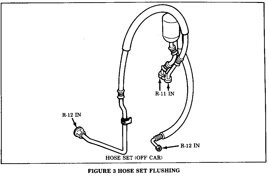
a) Force liquid R-11 into the discharge/suction hose compressor manifold block openings (do hoses one at a time) until clean R-11 flows from the other end of the hose, see figure 3. Also force liquid R-11 into the liquid lines and any other air conditioning hoses until clean R-11 flows from the other end of the line or hose. Flush off any debris that is on the expansion (orifice) tube. Either the small orifice nozzle flush gun J- 33883-15 or large orifice nozzle flush gun J-33883-50 may be used. Drain into a suitable waste container.
b) Cap all lines and hose ends with air conditioning hose end caps or appropriate plugs. Wait a minimum of 5 minutes before removing caps and draining the lines and hoses.
c) Force R-12 vapor into the hose ends (end opposite of the compressor manifold block) to purge the remaining R-11, see figure 3. Position the hose muffler such that all R-11 will be purged. Likewise, purge the liquid lines and other hoses with R-12. Use the large orifice nozzle flush gun J-33883-5Q or equivalent. Continue to blow R-12 vapor until no liquid is observed leaving the compressor manifold block, line or hose ends.
Where applicable, inspect for debris stuck on the high and low side refrigerant temperature sensors or pressure switches.
D. Accumulator (off car) -
a) Attach an extension tube to the accumulator inlet (female threads), invert the accumulator and drain the oil. Keep the accumulator capped when not draining or flushing.
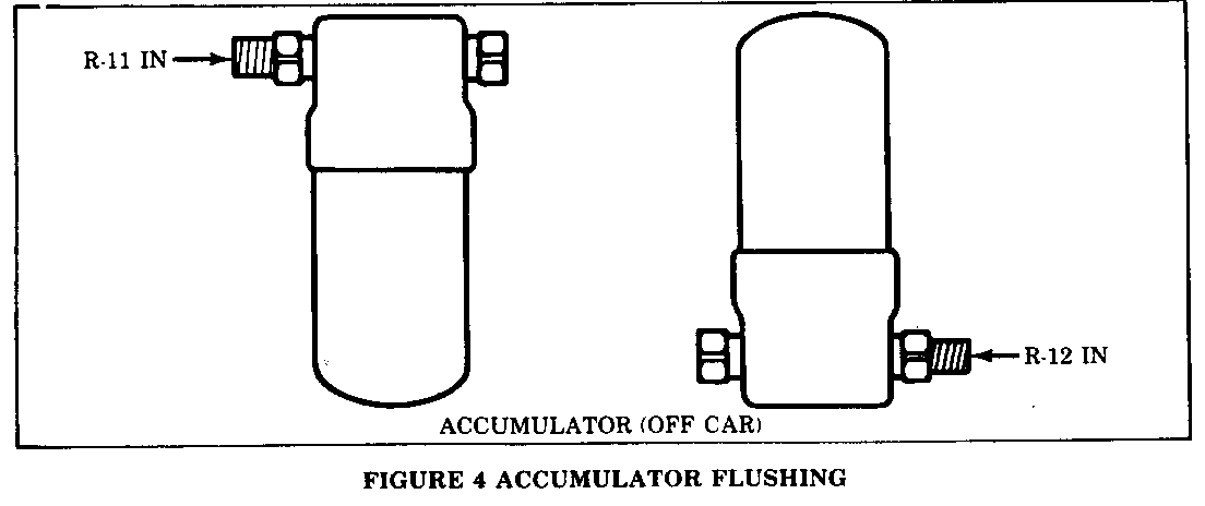
b) Set accumulator in the upright (as installed) position and force liquid R-11 into the accumulator outlet (male threads) until clean R-11 flows from the accumulator inlet (female threads) extension tube, see figure 4. Use the large orifice nozzle flush gun J-33883-50 or equivalent. Drain into a suitable waste container.
c) Cap both the accumulator outlet (male threads) and the extension tube with air conditioning hose end caps or appropriate plugs. Shake the accumulator and allow to soak for a minimum of 5 minutes before removing caps and draining the accumulator.
d) Invert the accumulator and force R-12 vapor into the accumulator outlet (male threads) to purge the remaining R-11, see figure 4. Use the large orifice nozzle flush gun J-33883-50 or equivalent. Continue to blow R-12 vapor until no liquid is observed leaving the accumulator inlet (female threads) extension tube.
e) Remove the extension tube, cap the accumulator and evacuate (just the accumulator using the shrader fitting) to remove any remaining liquid R-11. This will reduce the evacuation time required once the entire air conditioning system is assembled.
E. Compressor (off car) -
a) Mount the compressor in a vise over a drain pan using compressor holding fixture J-9396 (A-6), J-33026 (DA-6), J-25008-a (R-4) or J-34992 (V-5).
b) Invert the compressor and drain the oil through the suction and discharge ports. Also drain A-6 and V-5 compressors through the crankcase oil drain plug. See 'Refrigerant Oil Distribution' procedures as outlined in the appropriate Service Information Manual.
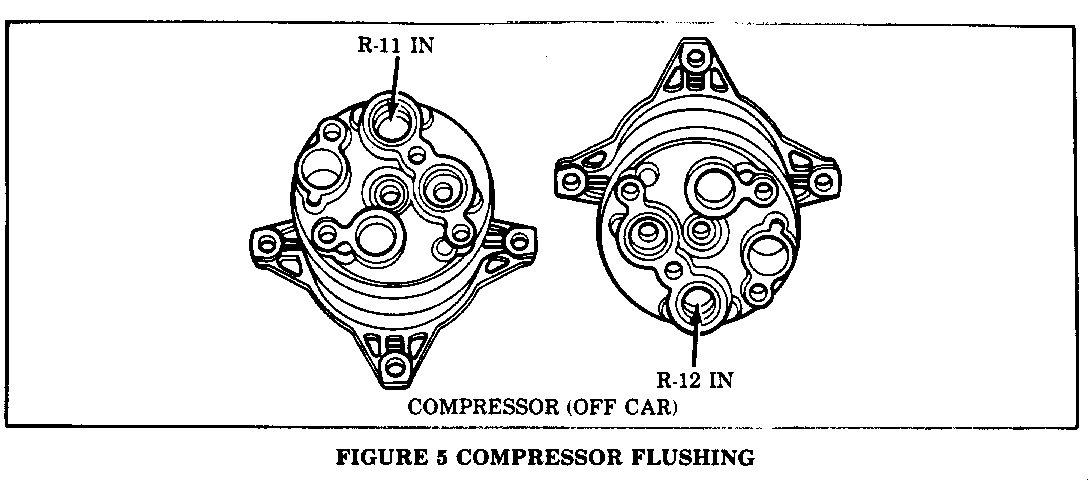
c) Set the compressor in the upright position (suction/discharge ports pointing upwards) and force liquid R-11 into the compressor suction port (larger internal opening) until clean R-11 flows from the discharge port (smaller internal opening), see figure 5. Use the large orifice nozzle, flush gun J-33883-50 or equivalent.
d) Turn the compressor by rotating the clutch driver for 1 or 2 turns, if possible. Do not force. R-11 will be pumped out of the discharge port (smaller internal opening).
e) Refill the compressor with R-11 (figure 5) and cap the suction/discharge ports with a compressor shipping cap. Rock or shake the compressor. Wait a minimum of 5 minutes before removing the cap, inverting the compressor (suction/discharge ports pointing towards the drain pan) and draining the compressor.
f) Force R-12 vapor into the compressor suction port (larger internal opening) to purge the remaining R-11, see figure 5. Use the large orifice nozzle flush gun J-33883-50 or equivalent. Continue to blow R-12 vapor until no liquid is observed leaving the discharge port (smaller internal opening).
5. Add 525 viscosity refrigerant oil to refrigerant system -
A. Drain as much oil as possible from the new or rebuilt compressor (see 'discharging, adding oil, evacuating' and charging' procedures as outlined in the appropriate Service Information Manual). A residual quantity of refrigerant oil will remain in the compressor that cannot be drained. A flushed compressor has no residual quantity of oil. The residual quantity of oil for a new or rebuilt compressor is as follows:
TOTAL SYSTEM CAPACITY RESIDUAL QUANTITY ADD QUANTITY --------------------- ----------------- ------------ A-6 - 330ml (11 fl. oz.) = 30ml (1 fl. oz.) + 300ml (10 fl. oz.) DA-6 - 240ml (8 fl. oz.) = 45ml (1.5 fl. oz.) + 195ml (6.5 fl. oz.) R-4 - 180ml (6 fl. oz.) = 30ml (1 fl. oz.) + 150ml (5 fl. oz.) V-5 - 240ml (8 fl. oz.) = 45ml (1.5 fl. oz.) + 195ml (6.5 fl. oz.)
Total system capacity is the proper refrigerant oil quantity for a new or totally flushed system. Add quantity is the proper refrigerant oil quantity for a new or totally flushed system with a new or rebuilt drained compressor. If the accumulator, condenser, evaporator or any other air conditioning component is not flushed or replaced, the above table is not applicable. See 'refrigerant oil distribution' procedures as outlined in the appropriate Service Information Manual to determine proper refrigerant oil quantity to be added.
B. Add the proper amount of new 525 viscosity refrigerant oil back into the compressor so that the total system capacity is correct. This will ensure the refrigerant system has the proper oil charge.
It is extremely important that the refrigerant system has the proper oil charge. Failure to maintain the proper oil charge may result in compressor damage and poor performance.
6. Reassemble air conditioning refrigerant system -
A. Install the air conditioning compressor on the vehicle.
B. Install the accumulator. The accumulator should remain capped until just prior to making final air conditioning system connections.
C. Replace the O-ring on the expansion (orifice) tube, if the expansion tube is reused. Lubricate the O-ring with 525 viscosity refrigerant oil. Insert the expansion tube into the liquid line (smaller screen end first) and push until the liquid line (smaller screen end first) and push until the expansion tube reaches a firm stop. This indicates proper seating of the O-ring.
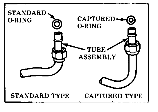
D. Install new GM approved service replacement air conditioning O-rings at all disassembled fittings, except where provided on new components. The connection fitting design should be carefully identified to ensure installation of the correct air conditioning service replacement O-ring, see figure 6. Some connections will implement a 'captured' O-ring design fitting that uses a groove to retain the O-ring, while others do not have a groove and use a 'non-captured' or 'standard' O-ring. Before installation, verify that both O-rings and fittings have not been nicked or deformed. Always slip the O-ring onto the flange tube to ensure proper, locating and sealing. Failure to use the proper service replacement parts and procedures may result in excessive refrigerant 12 leakage.
E. Connect all refrigerant lines and hoses. Tighten the connections following the 'handling of refrigerant lines and fittings' procedures as outlined in the appropriate Service Information Manual.
7. Evacuate and charge refrigerant system -
A. Evacuate the air conditioning system until a vacuum of 95-98 kPa (28- 29 in. hg.) or altitude adjusted is attained and can be held for 5 minutes, without the vacuum pump operating. See 'discharging, adding oil, evacuating and charging' procedures as outlined in the appropriate Service Information Manual. When evacuating, the inability to initially draw a vacuum does not necessarily indicate a system leak since proper evacuation vacuum levels will not be obtained until all of the liquid R-11 boils off and is evacuated. It is normal for the evacuation vacuum level to remain low (5-20 in. hg.) for a period of time (5 minutes or longer depending if liquid R- 11 was left in the system).
It is extremely important that the refrigerant system is properly evacuated. Failure to evacuate the refrigerant system may result in compressor damage and poor performance.
B. Insert a 0.48 kg. (1 lb.) charge of R-12 and leak check, if no leak is present., charge the air conditioning system with the recommended amount of R-12. See air conditioning system refrigerant capacity in the appropriate Service Manual.
Tools Required
1. Flush gun kit - J-33883-A
2. Air conditioning hose end caps and plugs
3. Assorted fill and drain tubes
4. Compressor holding fixture J-3396 (A-6), J-33026 (DA-6), J-25008-A (R- 4), or J-34992 (V-5).
Use of the R-11 in accordance with these instructions permit effective performance of the product without damaging the air conditioning system.
General Motors bulletins are intended for use by professional technicians, not a "do-it-yourselfer". They are written to inform those technicians of conditions that may occur on some vehicles, or to provide information that could assist in the proper service of a vehicle. Properly trained technicians have the equipment, tools, safety instructions and know-how to do a job properly and safely. If a condition is described, do not assume that the bulletin applies to your vehicle, or that your vehicle will have that condition. See a General Motors dealer servicing your brand of General Motors vehicle for information on whether your vehicle may benefit from the information.
