Circuit Description
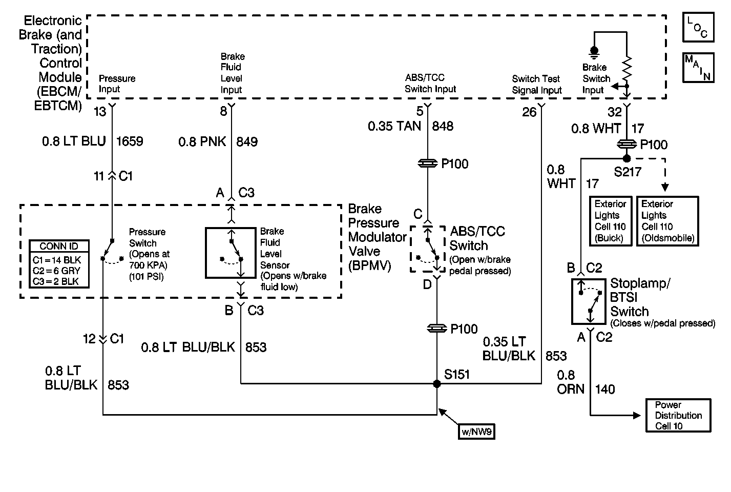
The EBCM/EBTCM monitors the brake pedal position using the brake travel switch. The switch, normally closed, opens when the brake pedal is pressed by 40 percent.
During most ABS braking conditions the EBCM/EBTCM turns ON the pump motor, replenishing the BPMV reservoir and applying fluid pressure to the master cylinder. This causes the brake pedal to rise gradually. The EBCM/EBTCM turns OFF the pump motor when the brake pedal height rises sufficiently to close the brake travel switch.
Conditions for Setting the DTC
The DTC C1272 sets when the EBCM/EBTCM detects that the brake travel switch CKT 848 is shorted to ground or open (with the brake pedal pressed).
Action Taken When the DTC Sets
The following actions are taken when the DTC sets:
| • | DTC C1272 is stored |
| • | The ABS is disabled |
| • | The ANTILOCK indicator lamp is turned on |
Conditions for Clearing the DTC
The DTC will clear under following conditions:
| • | Conditions for the malfunction are no longer present. Use the scan tool clear DTCs function. |
| • | 100 ignition switch key cycles have passed without detecting any malfunctions |
Diagnostic Aids
| • | The following conditions may be other possible causes of this malfunction: |
| - | The TCC/antilock switch circuit is open or shorted to ground |
| - | The BPMV fluid level switch circuit is shorted to ground |
| - | The ABS pump motor pressure switch circuit is shorted to ground |
| • | Perform a thorough inspection of the wiring and the connectors. |
| • | Failure to carefully inspect wiring may result in a misdiagnosis. A misdiagnosis may result in replacing parts without repairing the malfunction. |
Step | Action | Value(s) | Yes | No |
|---|---|---|---|---|
1 | Was the ABS Diagnostic System Check performed? | -- | Go to Step 2 | |
2 |
Is the brake switch operating properly? | -- | Go to Step 10 | Go to Step 3 |
3 |
Is the resistance less than the specified value? | 2 ohms | Go to Step 4 | Go to Step 13 |
4 | Use the J 39200 in order to measure the resistance between the J 38716 pinout box terminal 1 and terminal 5. Is the resistance less than the specified value? | 2 ohms | Go to Step 14 | Go to Step 5 |
5 | Use the J 39200 in order to measure the resistance between the J 38716 pinout box terminal 1 and terminal 26. Is the resistance less than the specified value? | 2 ohms | Go to Step 15 | Go to Step 6 |
6 |
Is the resistance less than the specified value? | 2 ohms | Go to Step 7 | Go to Step 11 |
7 |
Is the resistance less than the specified value? | 2 ohms | Go to Step 11 | Go to Step 8 |
8 |
Is the voltage greater than the specified value? | 1 V | Go to Step 12 | Go to Step 9 |
9 |
Is the resistance less than the specified value? | 2 ohms | Go to Step 21 | Go to Step 20 |
10 |
Does the DTC C1272 reset? | -- | Go to Step 21 | |
11 | Check the brake travel switch adjustment. Is the brake travel switch properly adjusted. | -- | Go to Step 16 | Go to Step 17 |
12 |
Is the voltage greater than the specified value? | 1 V | Go to Step 18 | Go to Step 19 |
13 | Repair the short to ground in CKT 1451. Refer to Wiring Repairs in Wiring Systems. Is the repair complete? | -- | -- | |
14 | Repair the short to ground in CKT 848. Refer to Wiring Repairs in Wiring Systems. Is the repair complete? | -- | -- | |
15 | Repair the short to ground in CKT 853. Refer to Wiring Repairs in Wiring Systems. Is the repair complete? | -- | -- | |
16 | Replace the brake travel switch. Refer to Brake Release Switch Replacement in Cruise Control. Is the repair complete? | -- | -- | |
17 | Repair the brake travel switch. Refer to Brake Release Switch Adjustment in Cruise Control. Is the repair complete? | -- | -- | |
18 | Repair the short to voltage in CKT 853. Refer to Wiring Repairs in Wiring Systems. Is the repair complete? | -- | -- | |
19 | Repair the short to voltage in CKT 848. Refer to Wiring Repairs in Wiring Systems. Is the repair complete? | -- | -- | |
20 | Repair the open or high resistance in CKT 848. Refer to Wiring Repairs in Wiring Systems. Is the repair complete? | -- | -- | |
21 | Replace the EBCM/EBTCM. Refer to Electronic Brake and Traction Control Module Replacement Is the repair complete? | -- | -- |
