CAMPAIGN:DRIVER'S WINDOW SWITCH OVERHEATING

1984-1985 ELDORADO CONVERTIBLES
TO: ALL GENERAL MOTORS DEALERS
CONDITION:
---------
General Motors of Canada has determined that a defect, which relates to motor vehicle safety may exist in some 1984 and 1985 Eldorado convertible models.
Water or snow dripping onto the driver's side window switch assemblies may cause an electrical short which can potentially cause the switches to overheat. This overheating may result in a fire in the door panel area.
DEALER ACTION
To correct this condition, Dealers are to replace the two window switch assemblies on all vehicles involved with those of a new design. In addition, on 1984 models only, Dealers will be required to replace the driver's side window switch connectors with newer type connectors.
VEHICLES INVOLVED:
All 1984 and 1985 Eldorado convertibles require this campaign. All affected vehicles have been identified by the VIN listing provided to involved Dealers with this bulletin. Any Dealer not receiving a listing was not shipped any of the affected vehicles.
DEALER CAMPAIGN RESPONSIBILITY:
Dealers are to service all vehicles subject to this campaign at no charge to owners, regardless of mileage, age of vehicle, or ownership, from this time forward.
Whenever a vehicle subject to this campaign is taken into your new or used vehicle inventory, or it is in your Dealership for service in the future, you should take the steps necessary to be sure the campaign correction has been made before reselling or releasing the vehicle.
Owners of vehicles recently sold from your new vehicle inventory are to be contacted by the Dealer, and arrangements made to make the required modification according to instructions contained in this bulletin.
CAMPAIGN PROCEDURE:
Refer to Section 4 of the Service Policies and Procedures Manual for the detailed procedure on handling Product Campaigns. Dealers are requested to complete the campaign on all transfers as soon as possible.
OWNER NOTIFICATION:
All owners of record at the time of campaign release are shown on the attached computer listing and have been notified by first class mail from General Motors. The listings provided are for campaign activity only and should not be used for any other purpose.
PARTS INFORMATION:
Parts required for this campaign should be purchased through regular channels follows: QUANTITY REQUIRED DESCRIPTION PART NUMBER PER VEHICLE ----------- ----------- ----------------
Window Switch Assembly 20683454 2
Connector-Window Switch 12048027 2 - (1984 models only) Assembly
Parts will not be available until after January 8, 1988.
PARTS AND LABOUR CLAIM INFORMATION:
Credit for the campaign work performed will be paid upon receipt of a properly completed campaign claim card, RAPID terminal or DCS transmission in accordance with the following:
Repair Code Description Time Allowance ----------- ----------- --------------
2A Replace Window Switch Assembly .4 (1985 Model) 20683454
3A Replace Two Connectors and .7 Window Switch Assembly (1984 Model) 20683454
Time allowance includes 0.1 hour for Dealer administrative detail associated with this campaign. Parts credit will be based on Dealer net plus 30% to cover parts handling.
SERVICE PROCEDURE:
1. Disconnect negative battery cable.
2. Remove driver's side armrest trim plate.
3. Disconnect both connectors from window switch/escutcheon assembly.
4. a. Unscrew both window switch assemblies from escutcheon.
b. Attach new window switch assemblies to escutcheon.
1985 models, proceed to step 6; 1984 models, proceed to step 5.
5. 1984 Model Connector Replacement --------------------------------
a. The connectors have a back cover (away from switch) which is heat staked in place. Pry the back cover off of the connector to expose the terminals, being careful not to damage any metal terminals. The metal terminals will now easily lift out of the connector. (See Figure 1.)
b. Insert the metal terminals into the two new connectors (P/N 12048027) until terminal "clicks" into place. (See Figure 2.) Be certain to insert the correct terminals into the correct connector cavities by referring to the table below and Figure 3.
Front Window Switch Connector
Cavity Wire colour Circuit No. ------ ----------- -----------
A Pink 76 B Dark Blue/White 166 c Tan 167 D Brown 165 E Dark Blue 164 F Black 150
Rear Window Switch Connector
Cavity Wire colour Circuit No. ------ ----------- -----------
A Pink 76 B Purple 169 C Dark Green 168 D Light Green 170 E Purple/White 171 F Black 150
6. Connect both connectors to switch/escutcheon assembly.
7. Install armrest trim plate.
8. Reconnect negative battery cable
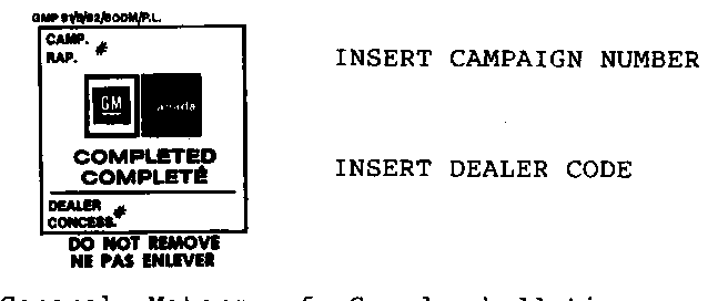
9. Install Campaign Completion Label.
INSTALLATION OF CAMPAIGN IDENTIFICATION LABEL
Clean surface of radiator upper mounting panel and apply a Campaign Identification Label. Make sure the correct campaign number is inserted on the label. This will indicate that the campaign has been completed.

General Motors bulletins are intended for use by professional technicians, not a "do-it-yourselfer". They are written to inform those technicians of conditions that may occur on some vehicles, or to provide information that could assist in the proper service of a vehicle. Properly trained technicians have the equipment, tools, safety instructions and know-how to do a job properly and safely. If a condition is described, do not assume that the bulletin applies to your vehicle, or that your vehicle will have that condition. See a General Motors dealer servicing your brand of General Motors vehicle for information on whether your vehicle may benefit from the information.
