For 1990-2009 cars only
Removal Procedure
- Turn the ignition OFF.
- Remove the air inlet duct. Refer to Air Cleaner Inlet Duct Replacement in Engine Controls - 3.6L (LY7).
- Relieve the fuel pressure. Refer to Fuel Pressure Relief in Engine Controls - 3.6L (LY7).
- Disconnect the fuel pressure and evaporative emission (EVAP) hoses from the engine. Refer to Metal Collar Quick Connect Fitting Service and to Plastic Collar Quick Connect Fitting Service in Engine Controls - 3.6L (LY7).
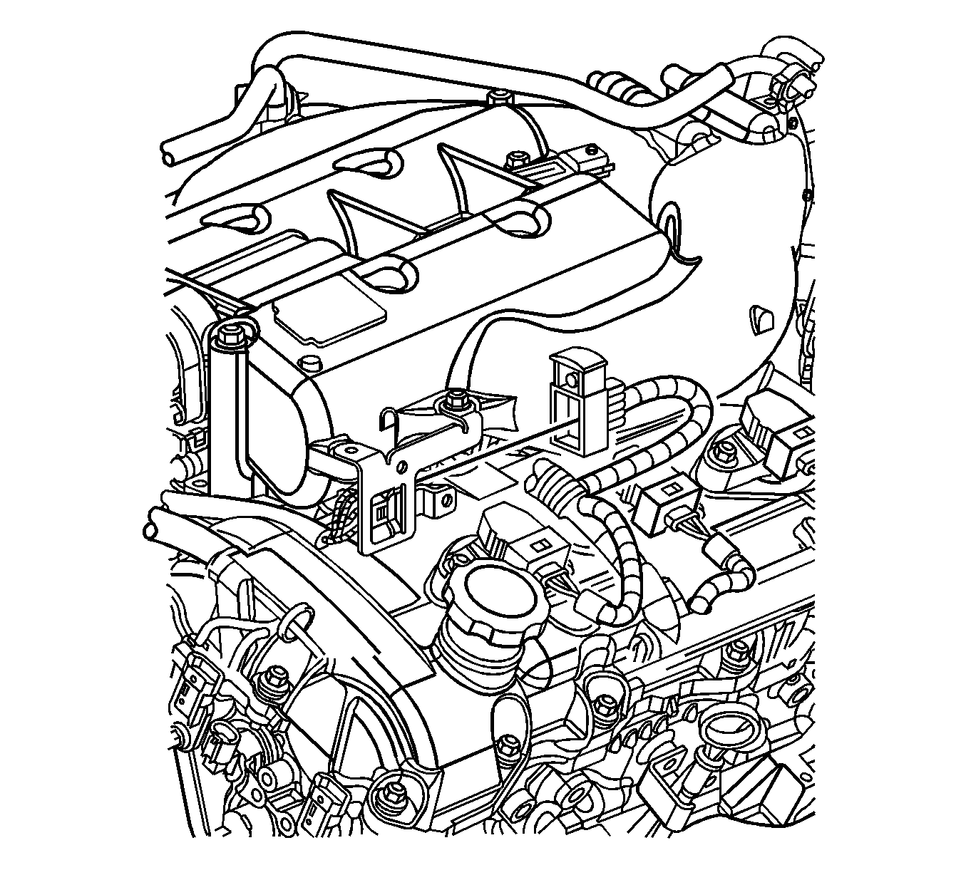
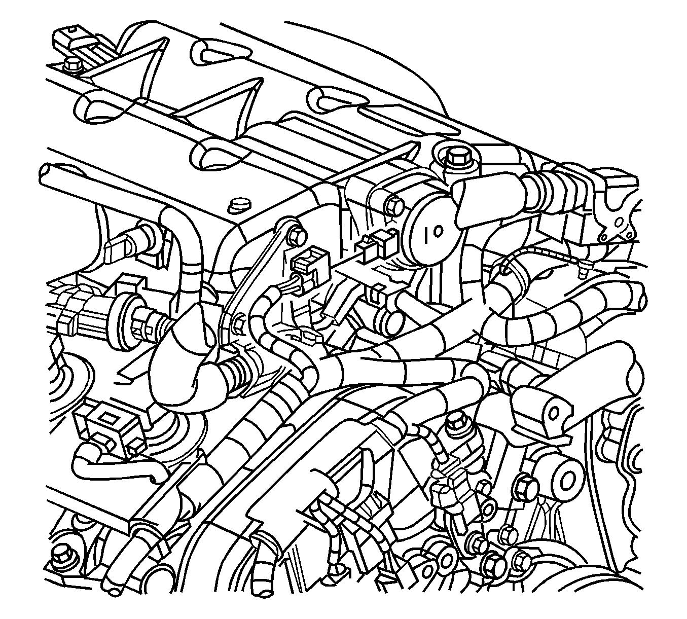
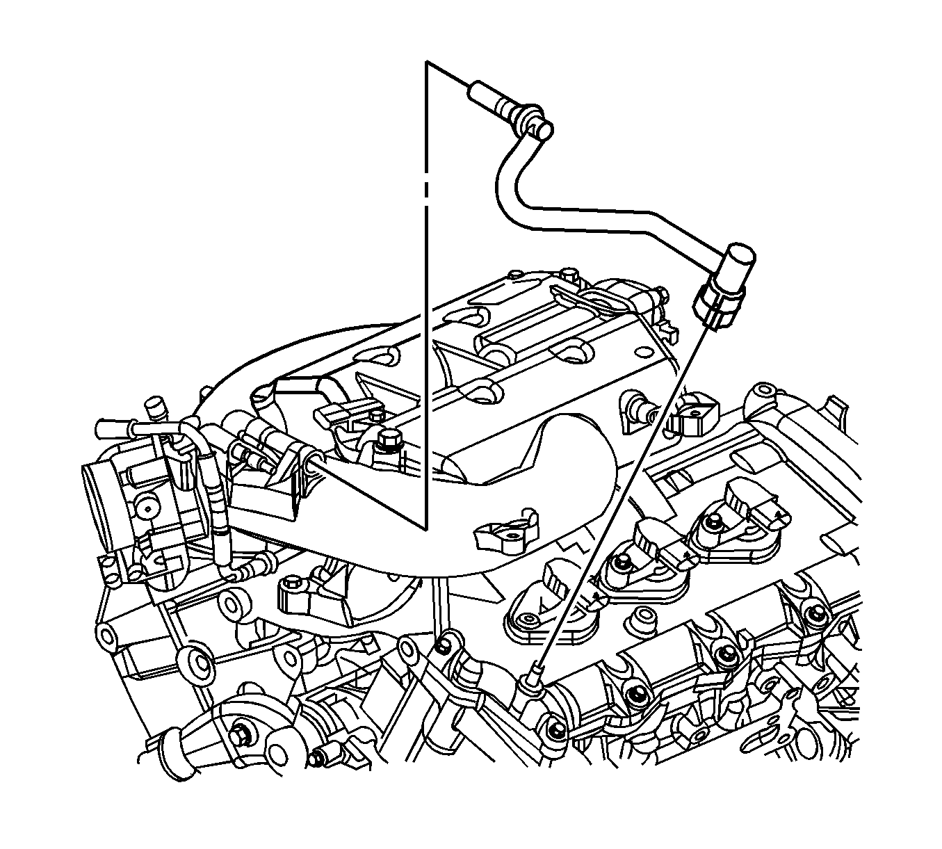
- Disconnect the barometric pressure (BARO) sensor electrical connector.
- Remove the ECM bracket with the ECM and reposition aside.
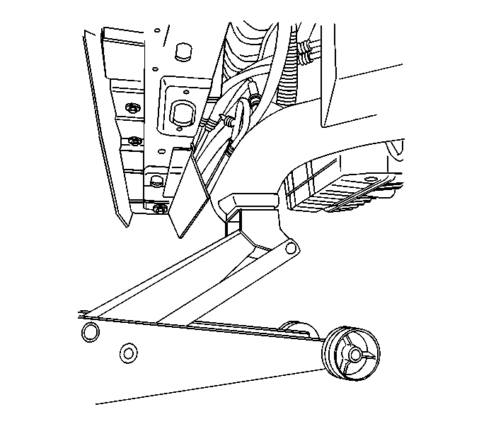
- Raise and support the vehicle. Refer to Lifting and Jacking the Vehicle in General Information.
- Disconnect the intermediate steering shaft from the steering gear. Refer to Intermediate Steering Shaft Replacement in Steering Wheel and Column.
- Remove and reposition the front portion of the front fender liners in order to gain access to the frame front bolts. Refer to Front Fender Liner Replacement in Body Front End.
- Lower the vehicle.
- Position a floor jack at the front center section of the frame in order to support the powertrain.
- Remove the frame front bolts.
- Carefully lower the powertrain or raise the vehicle enough to provide access.
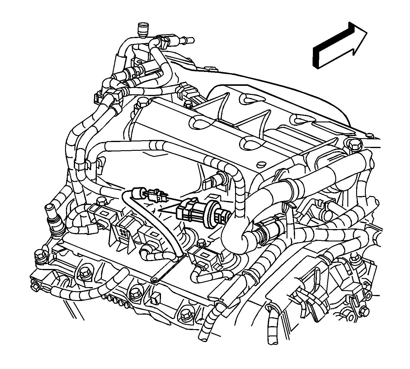
- Disconnect the purge solenoid electrical connector.
- Remove the wiring harness from the right side of the intake manifold.
- Disconnect the fuel injector electrical connector.
- Disconnect the intake manifold runner control solenoid electrical connector.
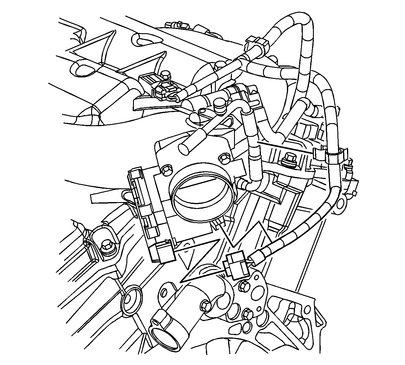
- Remove the throttle body electrical connector.
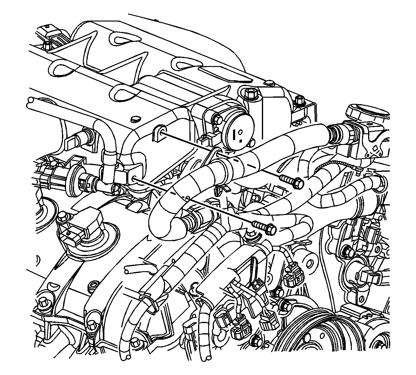
- Remove the brake booster vacuum hose from the intake manifold.
- Remove the positive crankcase ventilation (PCV) hose from the intake manifold and the cylinder head.
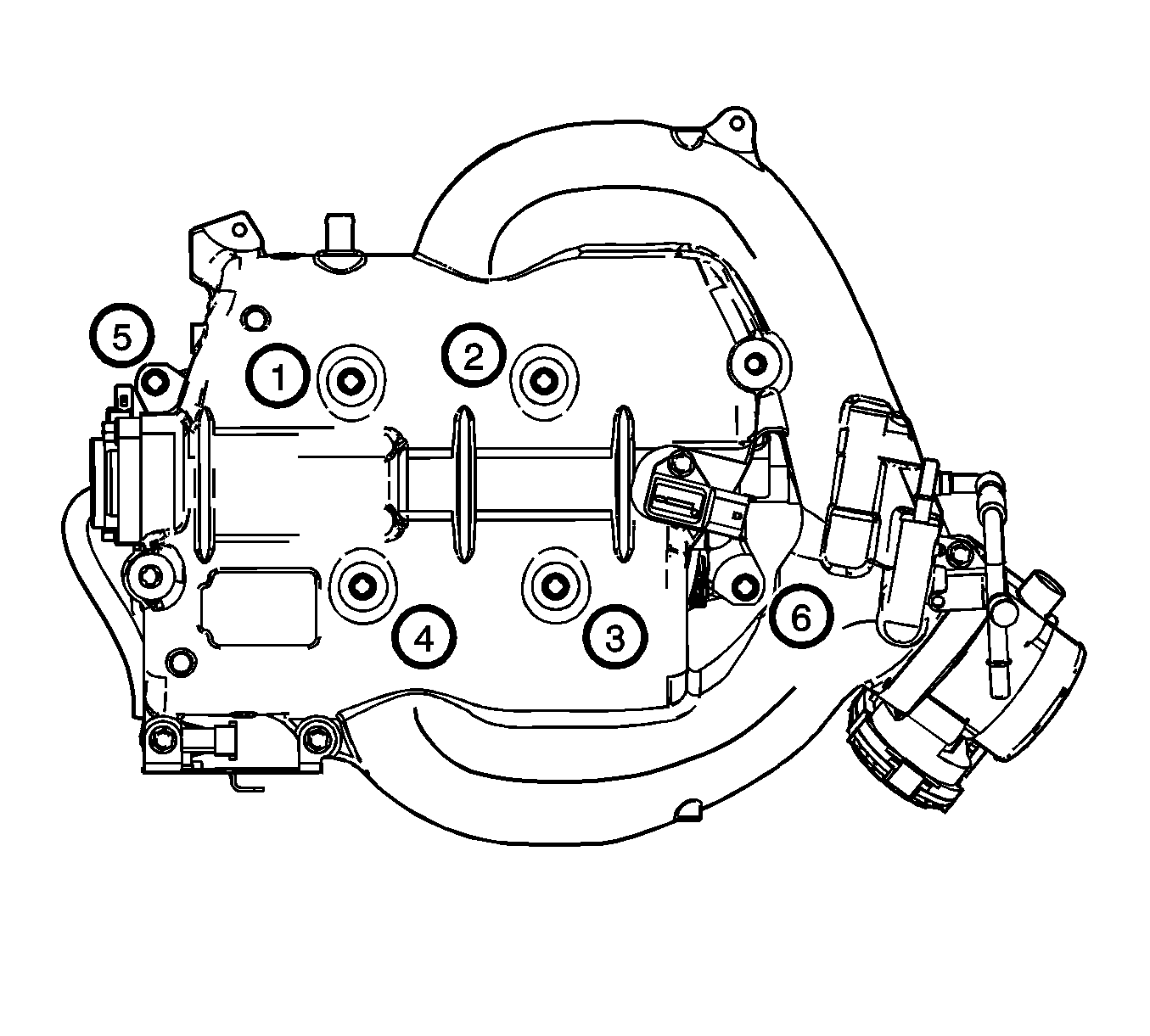
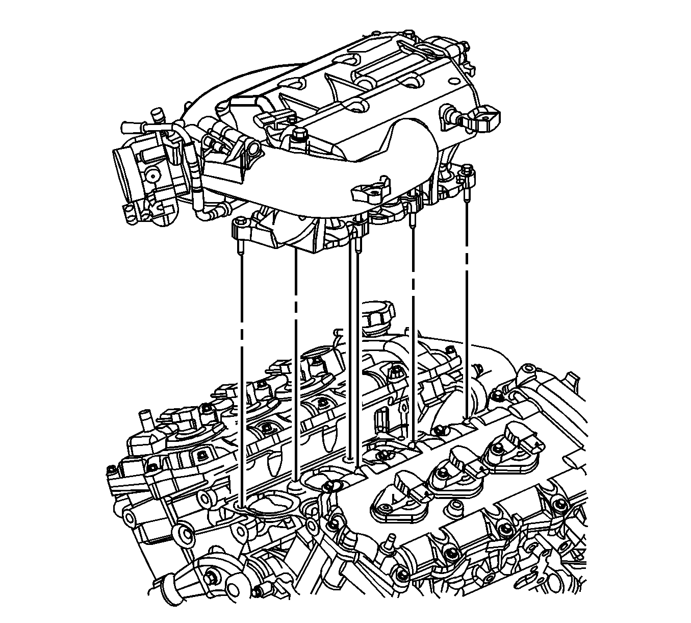
- Remove the intake manifold bolts (1-6).
- Remove the intake manifold.
- Disassemble the intake manifold as necessary. Refer to Intake Manifold Disassemble .
- Clean and inspect the intake manifold and the sealing surfaces. Refer to Intake Manifold Cleaning and Inspection .
Important: Do NOT disconnect the engine control module (ECM) electrical connectors.
Installation Procedure
- Assemble the intake manifold as necessary. Refer to Intake Manifold Assemble .
- Install the intake manifold. Refer to Intake Manifold Installation .
- Install the PCV hose to the intake manifold and the cylinder head.
- Install the brake booster vacuum hose to the intake manifold.
- Connect the throttle body electrical connector.
- Connect the intake manifold runner control solenoid electrical connector.
- Connect the fuel injector electrical connector.
- Install the wiring harness to the right side of the intake manifold.
- Connect the purge solenoid electrical connector.
- Carefully raise the powertrain or lower the vehicle in order to Install the frame bolts.
- Install the frame front bolts. Refer to Front Frame Replacement in Frame and Underbody.
- Remove the floor jack.
- Raise and support the vehicle. Refer to Lifting and Jacking the Vehicle in General Information.
- Install the front fender liners. Refer to Front Fender Liner Replacement in Body Front End.
- Connect the intermediate steering shaft to the steering gear. Refer to Intermediate Steering Shaft Replacement in Steering Wheel and Column.
- Lower the vehicle.
- Install the ECM bracket with the ECM.
- Connect the BARO sensor electrical connector.
- Connect the fuel pressure and EVAP hoses to the engine. Refer to Metal Collar Quick Connect Fitting Service and to Plastic Collar Quick Connect Fitting Service in Engine Controls - 3.6L (LY7).
- Install the air inlet duct. Refer to Air Cleaner Inlet Duct Replacement in Engine Controls - 3.6L (LY7).
Notice: Refer to Fastener Notice in the Preface section.
Tighten
Tighten the bracket bolts to 10 N·m
(89 lb in).
