Transmission Brace Replacement LA1
Removal Procedure
- Raise and support the vehicle. Refer to Lifting and Jacking the Vehicle in General Information.
- Remove the right front tire and wheel. Refer to Tire and Wheel Removal and Installation in Tires and Wheels.
- Remove the right engine splash shield. Refer to Engine Splash Shield Replacement in Body Front End.
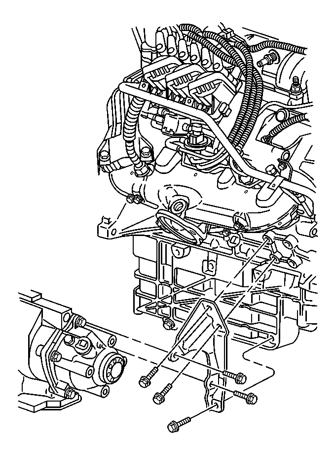
- Remove the transaxle brace bolts.
- Remove the transaxle brace.
Installation Procedure
- Position the transaxle brace to transaxle and engine.
- Hand start the bolts to the engine.
- Hand start the bolts to the transaxle.
- Install the brace bolts to the engine.
- Install the brace bolts to the transaxle.
- Install the right engine splash shield. Refer to Engine Splash Shield Replacement in Body Front End.
- Install the right front tire and wheel. Refer to Tire and Wheel Removal and Installation in Tires and Wheels.
- Lower the vehicle.
Notice: Use the correct fastener in the correct location. Replacement fasteners must be the correct part number for that application. Fasteners requiring replacement or fasteners requiring the use of thread locking compound or sealant are identified in the service procedure. Do not use paints, lubricants, or corrosion inhibitors on fasteners or fastener joint surfaces unless specified. These coatings affect fastener torque and joint clamping force and may damage the fastener. Use the correct tightening sequence and specifications when installing fasteners in order to avoid damage to parts and systems.
Tighten
Tighten the brace bolts to 43 N·m (32 lb ft).
Tighten
Tighten the brace bolts to 43 N·m (32 lb ft).
Transmission Brace Replacement LY7
Removal Procedure
- Raise and support the vehicle. Refer to Lifting and Jacking the Vehicle in General Information.
- Remove the right front tire and wheel. Refer to Tire and Wheel Removal and Installation in Tires and Wheels.
- Remove the right engine splash shield. Refer to Engine Splash Shield Replacement in Body Front End.
- Remove the transfer case brace. Refer to Support Brace Replacement in Transfer Case - Steyr.
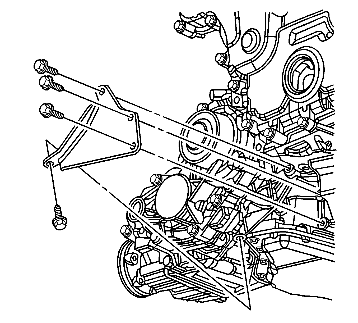
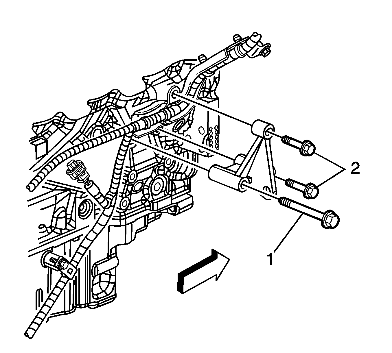
- Remove the transmission lower brace bolts.
- Remove the transmission lower brace.
- If you are servicing the transmission upper brace, it will be necessary to remove the powertrain (engine, transmission and frame). Then separate the transmission from the engine. Refer to Transmission Replacement .
- Remove the transmission upper brace bolts.
- Remove the transmission upper brace.
Installation Procedure
- Install the transmission upper brace.
- Install the transmission upper brace bolts.
- Install the transmission to the engine. Then install the powertrain (engine, transmission and frame) to the vehicle. Refer to Transmission Replacement .
- Install the transmission lower brace.
- Install the transmission lower brace bolts.
- Install the transfer case brace. Refer to Support Brace Replacement in Transfer Case - Steyr.
- Install the right engine splash shield. Refer to Engine Splash Shield Replacement in Body Front End.
- Install the right front tire and wheel. Refer to Tire and Wheel Removal and Installation in Tires and Wheels.
- Lower the vehicle.
Notice: Refer to Fastener Notice in the Preface section.
Tighten
Tighten the transmission upper brace outboard bolts (2)
to 23 N·m (17 lb ft).
Tighten
Tighten the transmission upper brace inboard bolt (1)
to 50 N·m (37 lb ft).
Tighten
Tighten the transmission lower brace bolts to 50 N·m
(37 lb ft).
