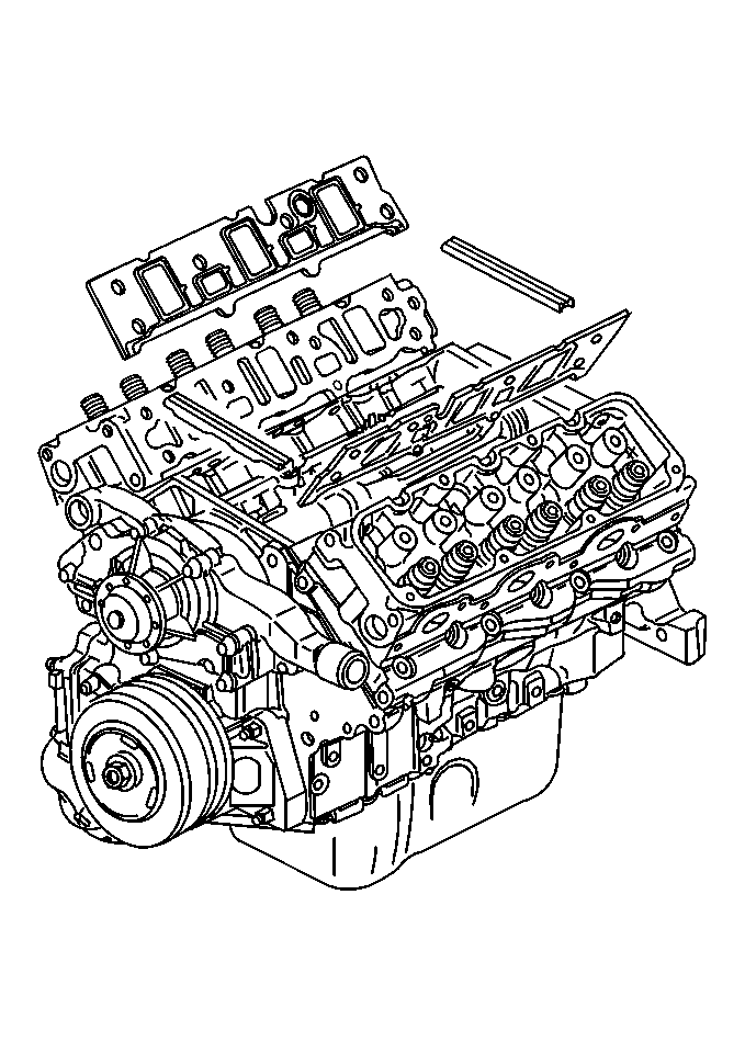
Lower Intake Manifold Replacement L36
Removal Procedure
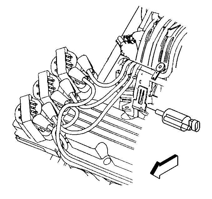
- Remove the evaporative emissions (EVAP) canister purge solenoid.
- Remove the upper intake manifold. Refer to Upper Intake Manifold Replacement .
- Remove the generator brace. Refer to Generator Brace Replacement in Engine Electrical.
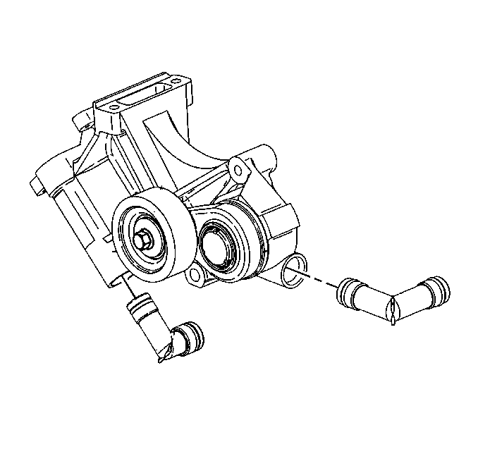
- Remove the drive belt tensioner with the heater water bypass inlet pipe. Refer to Drive Belt Tensioner Replacement .
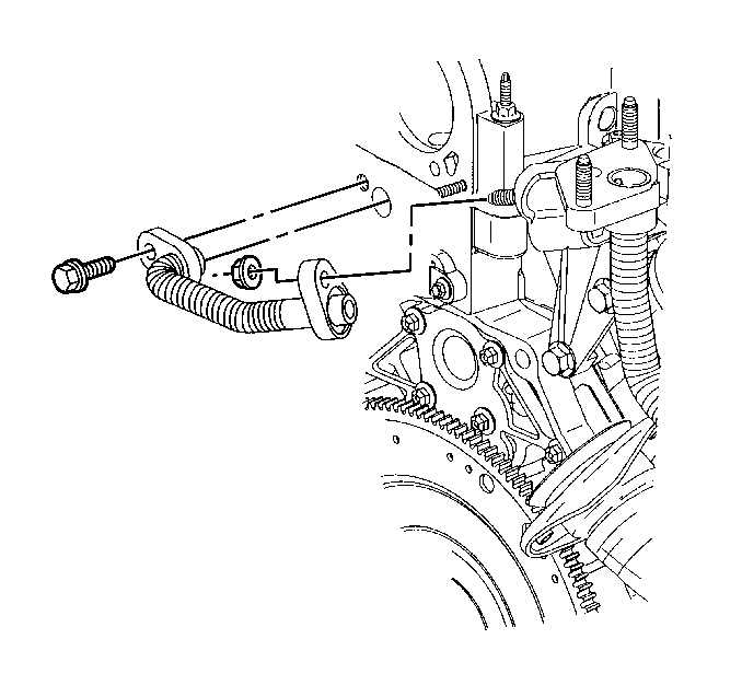
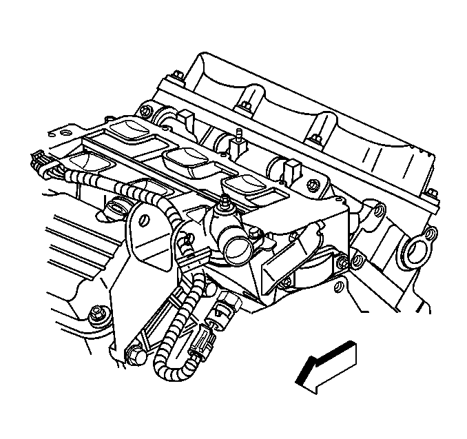
- Remove the exhaust gas recirculation (EGR) outlet pipe bolt from the lower intake manifold.
- Remove the EGR outlet pipe from the lower intake manifold.
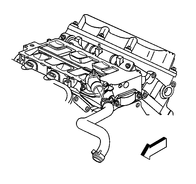
- Remove the radiator inlet hose from the water outlet housing. Refer to Radiator Inlet Hose Replacement in Engine Cooling.
- Disconnect the engine coolant temperature (ECT) sensor electrical connector.
- Remove the generator brace bracket bolts.
- Remove the generator brace bracket.
- Remove the lower intake manifold bolts.
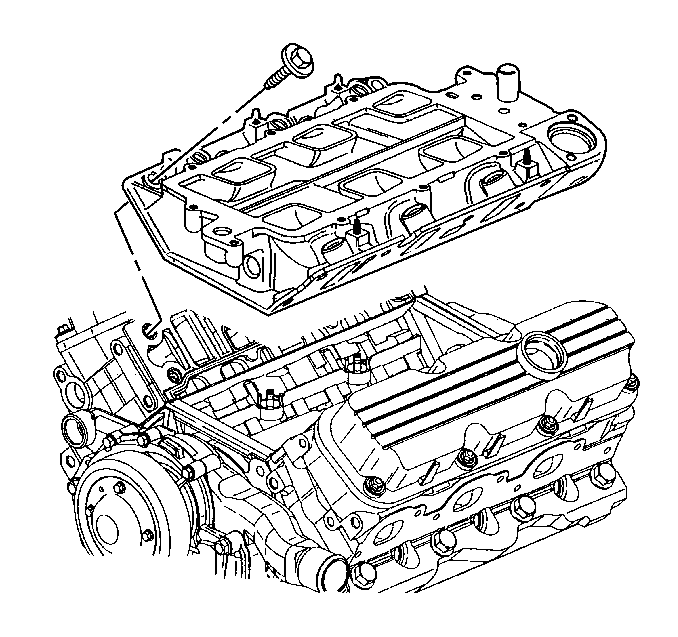
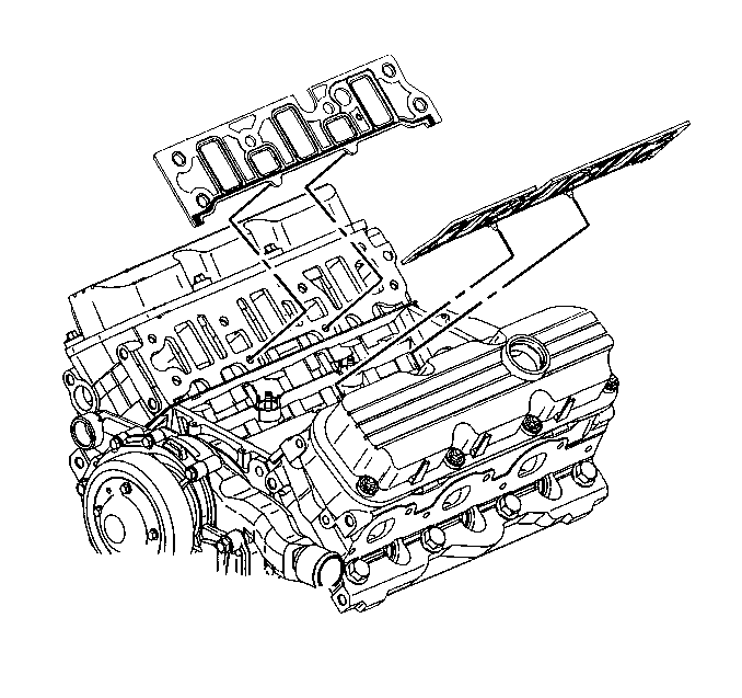
- Remove the lower intake manifold.
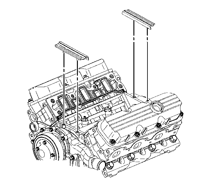
- Remove the lower intake manifold seals.
- Remove the lower intake manifold gaskets.
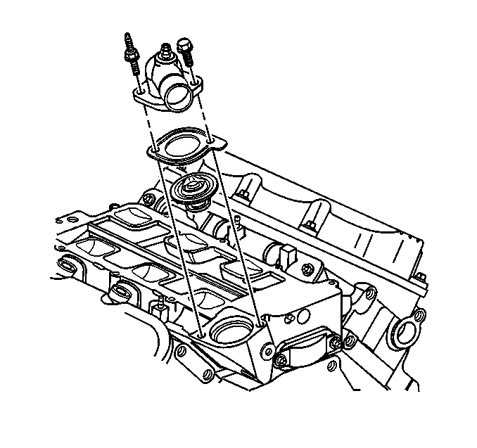
- If replacing the lower intake manifold, remove the water outlet housing bolt, stud and the water outlet housing.
- If replacing the lower intake manifold, remove the ECT sensor.
- Inspect the flatness of inlet flanges.
- Clean the intake manifold mating surfaces.
- Clean the intake manifold bolts and bolt holes of adhesive compound.
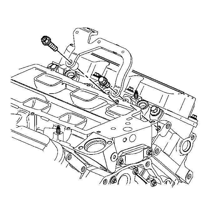
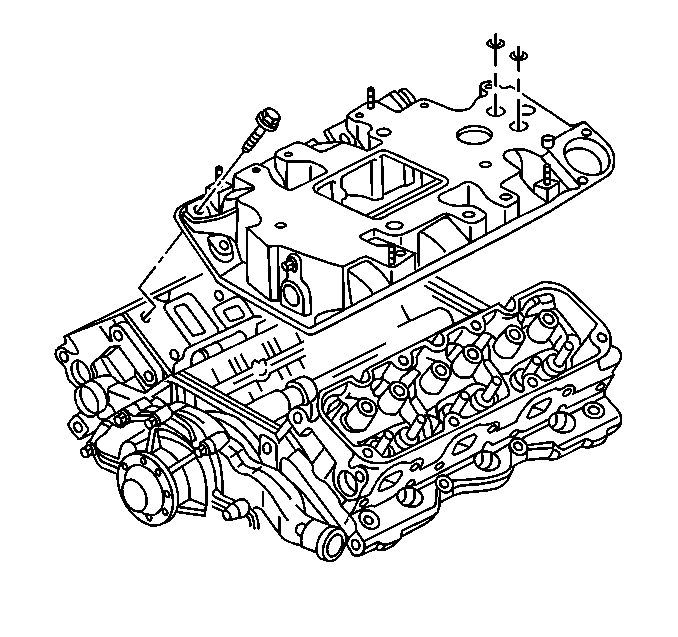
Notice: The two bolts which fasten the lower intake manifold to the cylinder head are accessible only after the upper intake is removed. The bolts are located in the right front and left rear corners of the lower intake manifold. Remove the upper intake manifold to service the lower intake.
Installation Procedure
- If removed, install the ECT sensor.
- If removed, install the thermostat, the gasket, and the water outlet housing.
- Install the water outlet housing bolt and the stud.
- Install the lower intake manifold gaskets.
- Apply sealer GM P/N 12346286 (Canadian P/N 10953472) or equivalent to the ends of the intake manifold seals.
- Install the lower intake manifold seals.
- Install the lower intake manifold.
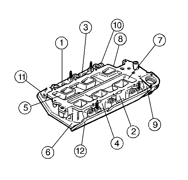
- Install the lower intake manifold bolts (1-12). Apply thread lock compound GM P/N 12345493 (Canadian P/N 10953488) or equivalent to the two hidden bolts and ensure they are installed.
- Install the generator brace bracket.
- Install the generator brace bracket bolts.
- Connect the ECT sensor electrical connector.
- Install the radiator inlet hose to the water outlet housing. Refer to Radiator Inlet Hose Replacement in Engine Cooling.
- Install the EGR outlet pipe to the lower intake manifold.
- Install the EGR outlet pipe bolt to the lower intake manifold.
- Install the drive belt tensioner. Refer to Drive Belt Tensioner Replacement .
- Install the generator brace. Refer to Generator Brace Replacement in Engine Electrical.
- Install the upper intake manifold. Refer to Upper Intake Manifold Replacement .
- Install the evaporative emissions (EVAP) canister purge solenoid.
- Inspect for fluid or vacuum leaks.
Notice: Use the correct fastener in the correct location. Replacement fasteners must be the correct part number for that application. Fasteners requiring replacement or fasteners requiring the use of thread locking compound or sealant are identified in the service procedure. Do not use paints, lubricants, or corrosion inhibitors on fasteners or fastener joint surfaces unless specified. These coatings affect fastener torque and joint clamping force and may damage the fastener. Use the correct tightening sequence and specifications when installing fasteners in order to avoid damage to parts and systems.
Tighten
Tighten the sensor to 25 N·m (18 lb ft).
Tighten
Tighten the bolt and the stud to 27 N·m (20 lb ft).
Notice: The two bolts which fasten the lower intake manifold to the cylinder head are accessible only after the upper intake is removed. The bolts are located in the right front and left rear corners of the lower intake manifold. Remove the upper intake manifold to service the lower intake.
Tighten
Tighten the lower intake manifold bolts in sequence to 15 N·m
(11 lb ft).
Tighten
Tighten the bolts to 50 N·m (37 lb ft).
Tighten
Tighten the bolt to 29 N·m (21 lb ft).
Lower Intake Manifold Replacement L67
Removal Procedure
- Drain the cooling system. Refer to Cooling System Draining and Filling in Engine Cooling.
- Remove the supercharger. Refer to Supercharger Replacement .
- Remove the radiator inlet hose from the water outlet housing. Refer to Radiator Inlet Hose Replacement in Engine Cooling.
- Remove the exhaust gas recirculation (EGR) outlet pipe bolt from the lower intake manifold.
- Remove the EGR outlet pipe from the lower intake manifold.
- Disconnect the engine coolant temperature (ECT) sensor electrical connector.
- Remove the lower intake manifold bolts.
- Remove the lower intake manifold. The coolant bypass tube will release from the intake manifold as the manifold is removed.
- Remove the lower intake manifold seals.
- Remove the lower intake manifold gaskets.
- If replacing the lower intake manifold, remove the water outlet housing and the thermostat.
- If replacing the lower intake manifold, remove the ECT sensor.
- Inspect the flatness of the inlet flanges.
- Clean the lower intake manifold mating surfaces.
- Clean the intake manifold bolts and the bolt holes of the adhesive compound.
Installation Procedure
- If removed, install the ECT sensor.
- If removed, install the thermostat, the gasket, and the water outlet housing.
- Install the water outlet housing bolt and the stud.
- Install the intake manifold gaskets.
- Apply sealer, GM P/N 12346286 (Canadian P/N 10953472) or equivalent, to the ends of the intake seals.
- Install the lower intake manifold seals.
- Align the coolant bypass tube with the opening in the manifold. Install the lower intake manifold.
- Install the lower intake manifold bolts.
- Connect the ECT sensor electrical connector.
- Install the EGR outlet pipe to the lower intake manifold.
- Install the EGR outlet pipe bolt.
- Install the radiator inlet hose to the water outlet housing. Refer to Radiator Inlet Hose Replacement in Engine Cooling.
- Install the supercharger. Refer to Supercharger Replacement .
- Fill the cooling system. Refer to Cooling System Draining and Filling in Engine Cooling.
- Inspect for fluid or vacuum leaks.
Notice: Use the correct fastener in the correct location. Replacement fasteners must be the correct part number for that application. Fasteners requiring replacement or fasteners requiring the use of thread locking compound or sealant are identified in the service procedure. Do not use paints, lubricants, or corrosion inhibitors on fasteners or fastener joint surfaces unless specified. These coatings affect fastener torque and joint clamping force and may damage the fastener. Use the correct tightening sequence and specifications when installing fasteners in order to avoid damage to parts and systems.
Tighten
Tighten the ECT sensor to 25 N·m (18 lb ft).
Tighten
Tighten the bolt and the stud to 27 N·m (20 lb ft).
Tighten
Tighten the lower intake manifold bolts from the center to the outside
in sequence to 15 N·m (11 lb ft).
Tighten
Tighten the bolt to 29 N·m (21 lb ft).
