Notice: Use the correct fastener in the correct location. Replacement fasteners
must be the correct part number for that application. Fasteners requiring
replacement or fasteners requiring the use of thread locking compound or sealant
are identified in the service procedure. Do not use paints, lubricants, or
corrosion inhibitors on fasteners or fastener joint surfaces unless specified.
These coatings affect fastener torque and joint clamping force and may damage
the fastener. Use the correct tightening sequence and specifications when
installing fasteners in order to avoid damage to parts and systems.
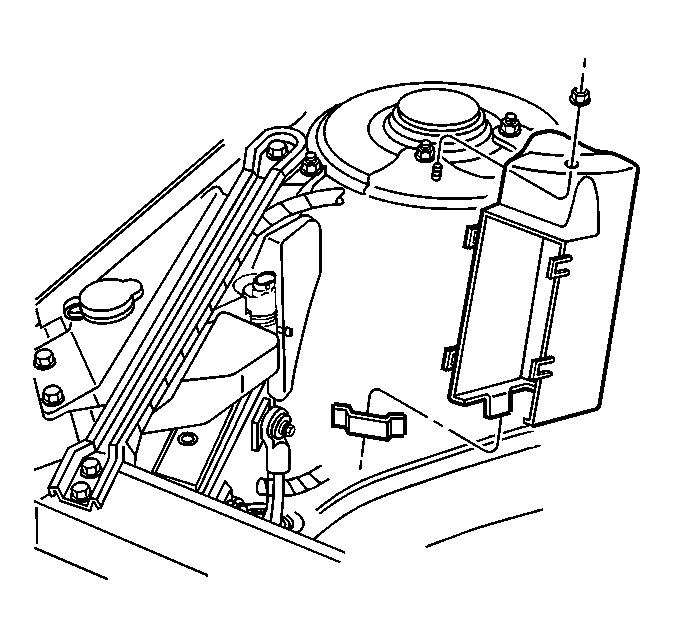
- If accessory wiring junction
block retainer installation is necessary, perform the following:
| 1.1. | Position the junction block retainer to the strut tower and insert
the lower tab on the retainer to the slot on the tower. |
| 1.2. | Install the junction block retainer to strut tower nut. |
Tighten
Tighten the underhood accessory wiring junction block retainer to strut
tower nut to 3 N·m (27 lb in).
| 1.3. | Position the positive battery cable lead end through the slot
in the junction block retainer, then secure the cable retainers. |
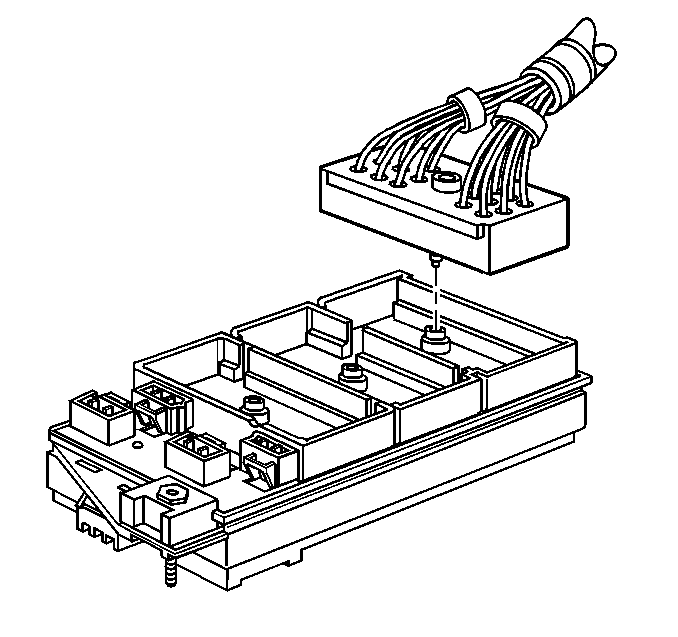
- Connect the forward lamp
wiring harness connector to the junction block.
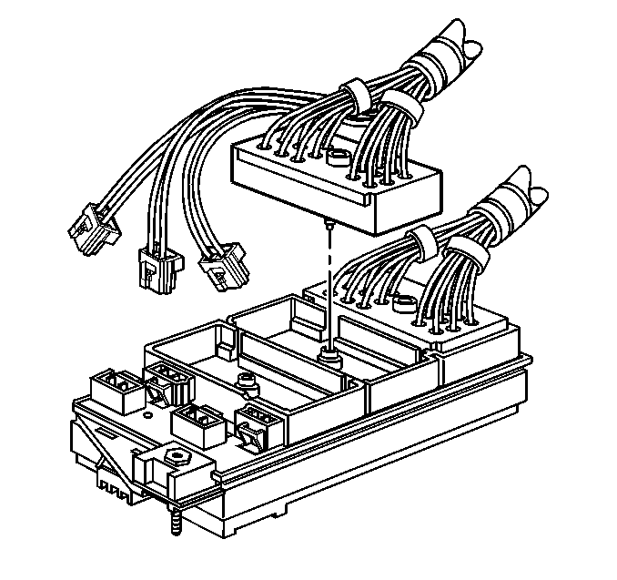
- Connect the IP wiring
harness connector to the junction block.
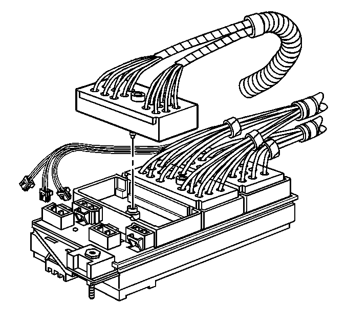
- Connect the engine wiring
harness connector to the junction block.
- Tighten the bolts retaining the engine, IP and forward lamp wiring
harness connectors to the junction block.
Tighten
Tighten the wiring harness connectors to underhood accessory wiring
junction block retaining bolts to 7 N·m (62 lb in).
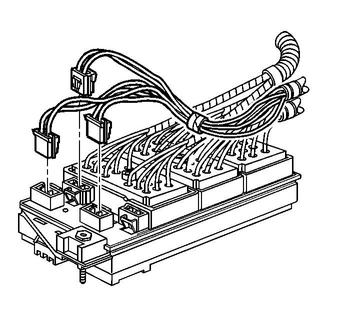
- Connect the IP wiring
harness individual connectors to the junction block.
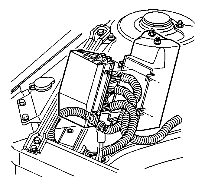
- Position the wiring harnesses
and the accessory wiring junction block to the junction block retainer, align
the four retaining tabs and press into place to secure the junction block.
- Secure the coolant recovery tank hose retainer to the junction
block.
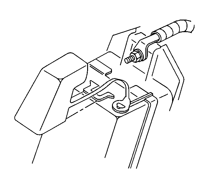
- Install the positive battery
cable lead to the stud on the underhood accessory wiring junction block,
then install the cable lead retaining nut.
Tighten
Tighten the positive battery cable lead to underhood accessory wiring
junction block retaining nut to 10 N·m (89 lb in).
- Install the remote positive battery cable stud cover.
- Connect the negative battery cable. Refer to
Battery Negative Cable Disconnection and Connection
in Engine Electrical.


