Removal Procedure
Caution: Fuel Vapors can collect while servicing fuel system parts in enclosed
areas such as a trunk. To reduce the risk of fire and increased exposure to
vapors:
• Use forced air ventilation such as a fan set outside
of the trunk. • Plug or cap any fuel system openings in order to reduce fuel vapor
formation. • Clean up any spilled fuel immediately. • Avoid sparks and any source of ignition. • Use signs to alert others in the work area that fuel system work
is in process.
Notice: Clean all of the following areas before performing any disconnections
in order to avoid possible contamination in the system:
• The fuel pipe connections • The hose connections • The areas surrounding the connections
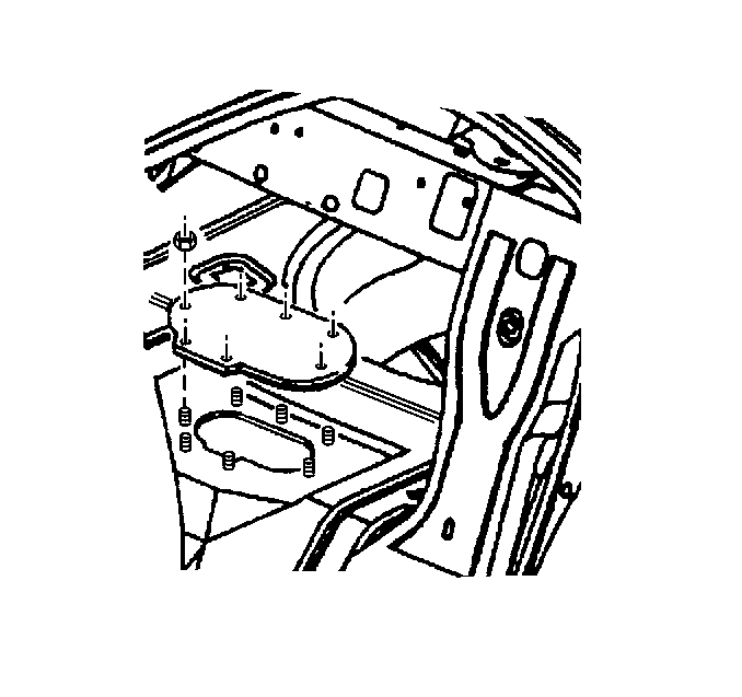
Important: For rear compartment accessible fuel sender assemblies, completely remove the rear compartment carpet before removing the fuel sender access panel.
Important: Always maintain cleanliness when servicing fuel system components.
- Relieve the fuel system fuel pressure. Refer to Fuel Pressure Relief .
- Remove the rear compartment trim panel. Refer to Rear Compartment Trim Panel Replacement in Body Rear End.
- Remove the nuts retaining the fuel sender access panel.
- Remove the fuel sender access panel.
- Disconnect the fuel tank pressure sensor electrical connector.
- Remove the fuel tank pressure sensor.
- Disconnect the fuel sender electrical connector.
- Clean the fuel pipes, and fuel sender assembly to prevent possible fuel contamination during removal.
- Disconnect the quick connect fittings at the fuel sender assembly. Refer to Plastic Collar Quick Connect Fitting Service .
- Hold down the fuel sender and remove the fuel sender retaining ring.
- Remove the fuel sender assembly.
- Clean the fuel sender assembly sealing surfaces.
- Inspect the fuel sender assembly sealing surfaces.
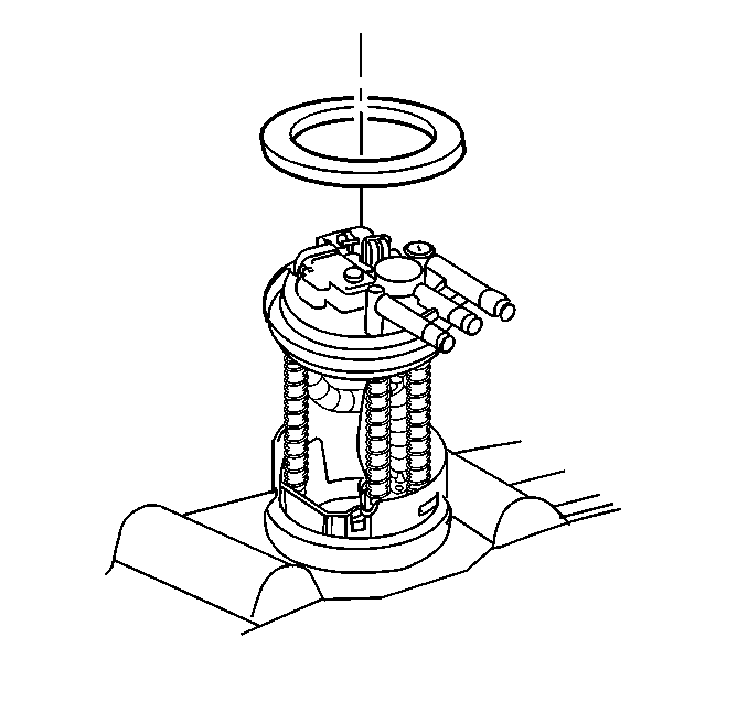
Important: The fuel sender assembly will spring-up when the retaining ring is removed.
Installation Procedure
Important: Care should be taken not to fold over or twist the fuel pump strainer when installing the fuel sender assembly, as this will restrict fuel flow. Also, assure that the fuel pump strainer does not block full travel of the float arm.
Important: Be sure that the fuel sender assembly retaining ring is fully seated within the tab slots on the fuel tank.
- Position the new fuel sender assembly seal on the fuel tank.
- Install the fuel sender assembly into the fuel tank.
- Install the fuel sender assembly retaining ring, while holding the fuel sender down.
- Connect the fuel sender electrical connector.
- Install the fuel tank pressure sensor.
- Connect the fuel tank pressure sensor electrical connector.
- Connect the quick connect fittings at the fuel sender assembly. Refer to Plastic Collar Quick Connect Fitting Service .
- Connect the negative battery cable. Refer to Battery Negative Cable Disconnection and Connection in Engine Electrical.
- Inspect for leaks.
- Install the fuel sender access panel.
- Install the nuts retaining the fuel sender access panel.
- Install the rear compartment trim panel. Refer to Rear Compartment Trim Panel Replacement in Body Rear End.
- Install the fuel injection sight shield. Refer to Fuel Injector Sight Shield Replacement in Engine Mechanical.
Important: Always replace the fuel sender seal when installing the fuel sender assembly.
| 9.1. | Turn ON the ignition for 2 seconds. |
| 9.2. | Turn OFF the ignition for 10 seconds. |
| 9.3. | Turn ON the ignition. |
| 9.4. | Inspect for fuel leaks. |
Notice: Use the correct fastener in the correct location. Replacement fasteners must be the correct part number for that application. Fasteners requiring replacement or fasteners requiring the use of thread locking compound or sealant are identified in the service procedure. Do not use paints, lubricants, or corrosion inhibitors on fasteners or fastener joint surfaces unless specified. These coatings affect fastener torque and joint clamping force and may damage the fastener. Use the correct tightening sequence and specifications when installing fasteners in order to avoid damage to parts and systems.
Tighten
Tighten the fuel sender access panel nuts to 10 N·m (89 lb in).
