Fuel Pump Electrical Circuit Diagnosis VIN K
Refer to
Cell 20: Fuel Control (VIN 1)
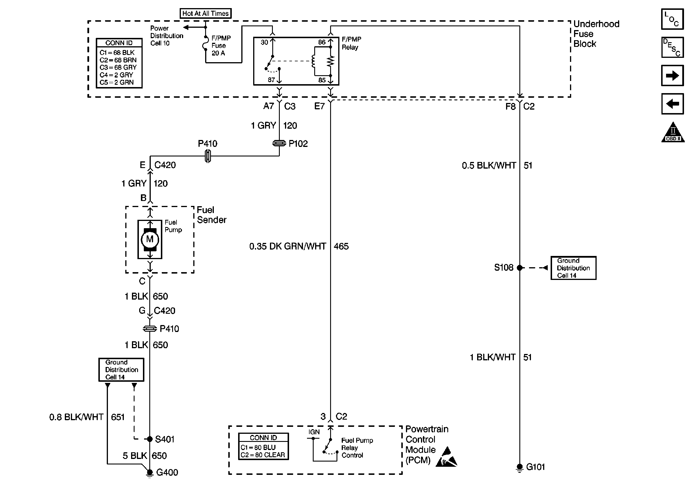
for a wiring diagram.
Circuit Description
When the ignition switch is first turned on, the PCM energizes the fuel pump relay which applies power to the in-tank fuel pump. The fuel pump relay will remain on as long as the engine is running or cranking and the PCM is receiving reference pulses. If no reference pulses are present, the PCM de-energizes the fuel pump relay within 2 seconds after the ignition is turned on or the engine is stopped.
The fuel pump delivers fuel to the fuel rail and injectors, then to the fuel pressure regulator. The fuel pressure regulator controls fuel pressure by allowing excess fuel to be returned to the fuel tank.
Diagnostic Aids
An intermittent may be caused by a poor connection, rubbed through wire insulation or a wire broken inside the insulation. Check for a poor connection or damaged harness. A blown fuse may be the result, so always check for possible causes. Inspect the PCM harness and connectors for the following items:
| • | Improper mating |
| • | Broken locks |
| • | Improperly formed or damaged terminals |
| • | Poor terminal to wire connections |
| • | Damaged harnesses |
Test Description
The numbers below refer to the step numbers on the Diagnostic Table:
-
Verifies that the fuel pump feed circuit is OK between the fuel pump relay and the fuel pump, and that the fuel pump can deliver adequate pressure to the fuel rail.
-
Checks the ignition feed circuit to the fuel pump relay.
-
Checks the fuel pump feed circuit for a short to battery positive voltage.
-
Checks whether the problem is being caused by an open in the fuel pump feed circuit or the fuel pump ground circuit.
Step | Action | Value(s) | Yes | No |
|---|---|---|---|---|
1 | Was the Powertrain OBD System Check performed? | -- | ||
Is proper fuel pressure indicated | 284-325 kPa (41-47 psi) | |||
Does the test lamp illuminate? | -- | |||
Does the test lamp illuminate? | -- | |||
5 |
Did you find and correct the condition? | -- | -- | |
6 |
Did you find and correct the condition? | -- | ||
7 | Replace the underhood wiring junction block. Did you find and correct the condition? | -- | -- | |
Probe the fuel pump feed circuit at the modular fuel sender harness connector with a test lamp to chassis ground. Does the test lamp illuminate? | -- | |||
9 |
Did you find and correct the condition? | -- | ||
10 |
Did you find and correct the condition? | -- | ||
11 | Replace the fuel pump relay. Refer to Fuel Pump Relay Replacement . Did you complete the replacement? | -- | -- | |
12 |
Did you complete the replacement? | -- | -- | |
13 |
Is proper fuel pressure indicated? | 284-325 kPa (41-47 psi) | System OK |
Fuel Pump Electrical Circuit Diagnosis VIN 1
Refer to
Cell 20: Engine Controls --Fuel Control, VIN 1
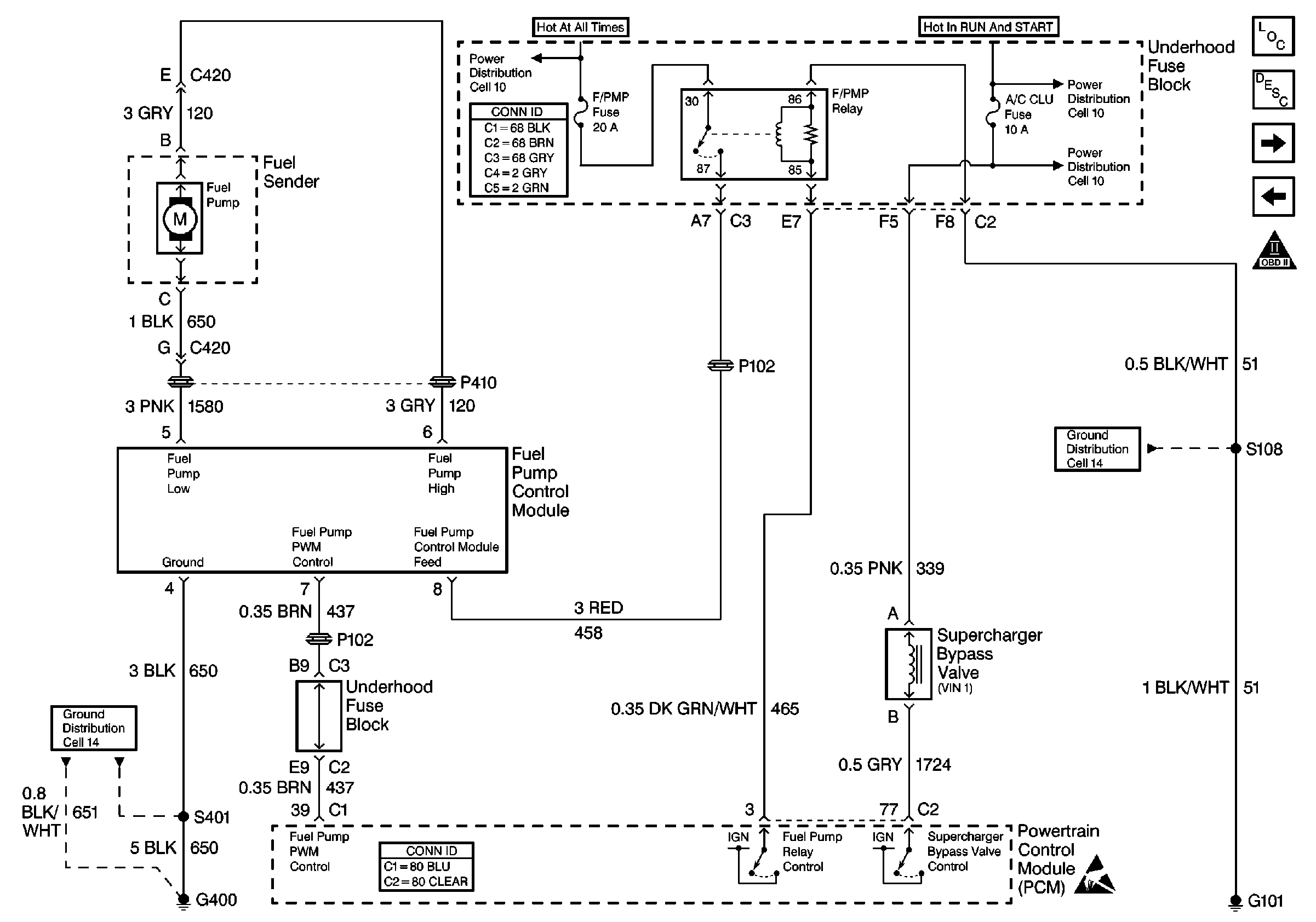
for a wiring diagram.
Circuit Description
When the ignition switch is first turned on, the PCM energizes the fuel pump relay which applies power to the in-tank fuel pump. The fuel pump relay will remain on as long as the engine is running or cranking and the PCM is receiving reference pulses. If no reference pulses are present, the PCM de-energizes the fuel pump relay within 2 seconds after the ignition is turned on or the engine is stopped.
The fuel pump delivers fuel to the fuel rail and injectors, then to the fuel pressure regulator. The fuel pressure regulator controls fuel pressure by allowing excess fuel to be returned to the fuel tank.
Diagnostic Aids
An intermittent may be caused by a poor connection, rubbed through wire insulation or a wire broken inside the insulation. Check for a poor connection or damaged harness. A blown fuse may be the result, so always check for possible causes. Inspect the PCM harness and connectors for the following items:
| • | Improper mating |
| • | Broken locks |
| • | Improperly formed or damaged terminals |
| • | Poor terminal to wire connections |
| • | Damaged harnesses |
Test Description
The numbers below refer to the step numbers on the Diagnostic Table:
-
Verifies that the fuel pump feed circuit is OK between the fuel pump relay and the fuel pump, and that the fuel pump can deliver adequate pressure to the fuel rail.
-
Checks the ignition feed circuit to the fuel pump relay.
-
Checks the fuel pump feed circuit for a short to battery positive voltage.
-
Checks whether the problem is being caused by an open in the fuel pump feed circuit or the fuel pump ground circuit.
Step | Action | Value(s) | Yes | No |
|---|---|---|---|---|
1 | Was the Powertrain OBD System Check performed? | -- | ||
Is proper fuel pressure indicated | 284-325 kPa (41-47 psi) | |||
Does the test lamp illuminate? | -- | |||
Does the test lamp illuminate? | -- | |||
5 |
Did you find and correct the condition? | -- | -- | |
6 |
Did you find and correct the condition? | -- | ||
7 | Replace the underhood wiring junction block. Did you find and correct the condition? | -- | -- | |
Probe the fuel pump feed circuit at the modular fuel sender harness connector with a test lamp to chassis ground. Does the test lamp illuminate? | -- | |||
9 |
Did you find and correct the condition? | -- | ||
10 |
Did you find and correct the condition? | -- | ||
11 | Replace the fuel pump relay. Refer to Fuel Pump Relay Replacement . Did you complete the replacement? | -- | -- | |
12 |
Did you complete the replacement? | -- | -- | |
13 |
Is proper fuel pressure indicated? | 284-325 kPa (41-47 psi) | System OK |
