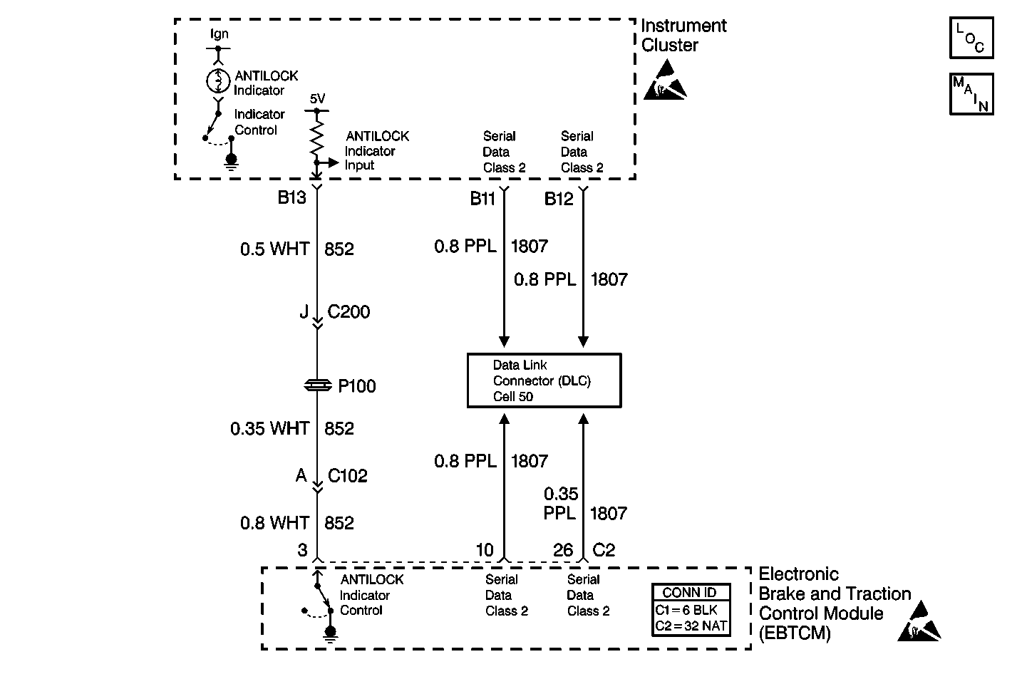
Circuit Description
The instrument cluster controls the operation of the ABS indicator. The EBCM/EBTCM reports the desired status of the ABS indicator via class 2 serial data messages. The ABS indicator signal circuit is a back-up reporting circuit to the class 2 serial data messages. The EBCM/EBTCM supplies ground through the circuit when the ABS is operating properly. When there is a problem with ABS that should turn on the ABS indicator, the EBCM/EBTCM opens the ABS indicator signal circuit. If there is a problem with the ABS class 2 serial data messages, the instrument cluster uses the ABS indicator signal to determine if the ABS indicator should be illuminated. Using the serial data messages and back-up circuit, the instrument cluster decides whether to turn on the ABS indicator.
Conditions for Setting the DTC
The EBCM/EBTCM commands the ABS indicator on when an open, a short to ground, or a short to voltage is detected.
Action Taken When the DTC Sets
| • | A DTC C1211 is stored |
| • | The ABS is not disabled |
| • | The ABS indicator remains off |
Conditions for Clearing the DTC
| • | The condition for the DTC is no longer present and you used the scan tool Clear DTC function. |
| • | The EBCM/EBTCM does not detect the DTC in 50 drive cycles. |
Diagnostic Aids
| • | Thoroughly inspect the wiring and the connectors. Failure to carefully and fully inspect the wiring and the connectors can result in misdiagnosis. Misdiagnosis may cause replacement of parts without repairing the malfunction. |
| • | If an intermittent malfunction exists, refer to Testing for Electrical Intermittents in Wiring Systems. |
Test Description
The numbers below refer to the step numbers on the diagnostic table.
-
This step determines whether the IPC can operate the ABS indicator.
-
This step tests for a short to ground in CKT 852.
-
This step tests for a short to voltage in CKT 852.
-
This step tests for an open in CKT 852.
Step | Action | Value(s) | Yes | No |
|---|---|---|---|---|
1 | Was the ABS Diagnostic System Check performed? | -- | Go to Step 2 | Go to Diagnostic System Check |
2 |
Is DTC U1300, or U1301 set? | -- | Go to Diagnostic System Check - Data Link Communications in Wiring Systems | Go to Step 3 |
Does the ABS indicator turn on then off? | -- | Go to Step 4 | Go to Step 11 | |
Is the resistance within specifications? | OL (infinite) | Go to Step 6 | Go to Step 5 | |
5 | Repair the short to ground in CKT 852. Refer to Wiring Repairs in Wiring Systems. Is the repair complete? | -- | Go to Diagnostic System Check | -- |
Is the voltage less than the specified value? | 1.0 V | Go to Step 8 | Go to Step 7 | |
Is the resistance less than the specified value? | 5 ohms | Go to Step 10 | Go to Step 9 | |
8 | Repair the short to voltage in CKT 852. Refer to Wiring Repairs in Wiring Systems. Is the repair complete? | -- | Go to Diagnostic System Check | -- |
9 | Repair the open in CKT 852. Refer to Wiring Repairs in Wiring Systems. Is the circuit repair complete? | -- | Go to Diagnostic System Check | -- |
10 | Replace the EBCM/EBTCM. Refer to Electronic Brake Control Module Replacement . Is the replacement complete? | -- | Go to Diagnostic System Check | -- |
11 | Suspect the IPC. Refer to Diagnostic System Check - Instrument Cluster in Instrument Panel, Gauges, and Console. Is the diagnosis complete? | -- | Go to Diagnostic System Check | -- |
