Removal Procedure
- Remove the bottom pan and seal, scavenge screens, and the lip seals. Refer to Transfer Oil Pump Inlet Screen and Pipe Seal Replacement .
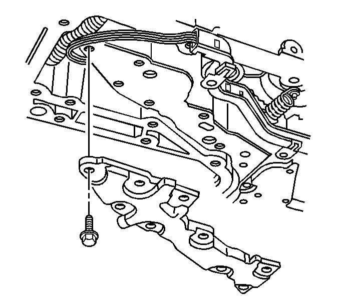
- Remove the bolts from the oil transfer plate and the wire harness extension retaining clip.
- Remove the oil transfer plate.
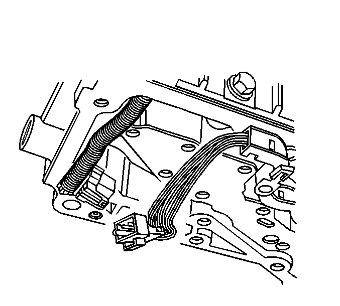
- Disconnect the wire harness extension from the wire harness assembly.
- Use a small screwdriver in order to disconnect the manual valve link retainer (2) from the manual valve link (3).
- Remove the manual valve link (3) from the inside detent lever (1).
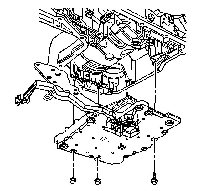
- Remove the two nuts and fourteen bolts from the lower valve assembly.
- Remove the lower valve assembly (consisting of the channel plate, control valve body, accumulator assembly, and wire harness extension) from the transaxle case as a single unit.
- For disassembly of the lower control valve body assembly. Refer to Control Valve Lower Body Disassemble in Automatic Transaxle - 4T80-E Unit Repair Manual.
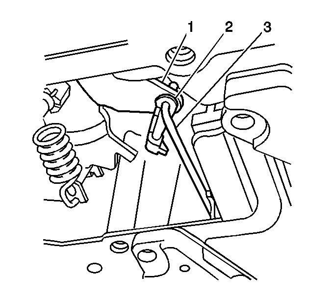
Important: Do not reuse the retainer (2), it must be replaced.
Important: Do not pry the internal mode switch assembly.
Installation Procedure
- For assembly of the lower control valve body assembly. Refer to Lower Control Valve Body and Internal Mode Switch Installation in Automatic Transaxle - 4T80-E Unit Repair Manual.
- Install the lower valve assembly (consisting of the channel plate, control valve body, accumulator assembly, and the wire harness extension) to the transaxle case as a single unit.
- Place the Lower valve assembly over the forward support studs.
- Hand start the bolts and nuts to the lower valve assembly.
- Install the oil transfer plate.
- Position the wire harness extension retaining clip over the appropriate bolt hole in the oil transfer plate.
- Hand start the bolts to the oil transfer plate.
- Insert the manual valve link (3) into the inside detent lever (1).
- Connect the wire harness extension to the wire harness assembly.
- Install the bottom pan and seal, the scavenger screens, and the lip seals. Refer to Transfer Oil Pump Inlet Screen and Pipe Seal Replacement .
- Reset the TAP values. Refer to Transmission Adaptive Functions .
Notice: Use the correct fastener in the correct location. Replacement fasteners must be the correct part number for that application. Fasteners requiring replacement or fasteners requiring the use of thread locking compound or sealant are identified in the service procedure. Do not use paints, lubricants, or corrosion inhibitors on fasteners or fastener joint surfaces unless specified. These coatings affect fastener torque and joint clamping force and may damage the fastener. Use the correct tightening sequence and specifications when installing fasteners in order to avoid damage to parts and systems.
Tighten
Tighten the Lower valve assembly and the oil transfer plate bolts and nuts to 11 N·m (97 lb in).
Important: Do not reuse retainer (2), it must be replaced.
Clip the manual valve link retainer (2) onto the manual valve link (3).
Important: It is recommended that transmission adaptive pressure (TAP) information be reset.
Resetting the TAP values using a scan tool will erase all learned values in all cells. As a result, The ECM, PCM or TCM will need to relearn TAP values. Transmission performance may be affected as new TAP values are learned.