For 1990-2009 cars only
Tools Required
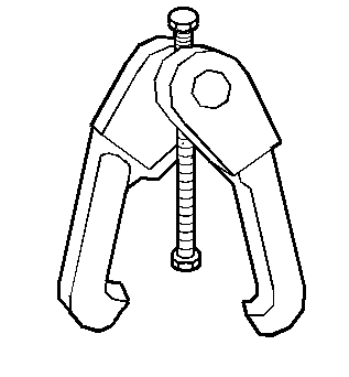
J 24319-B Universal Steering Linkage Puller
Removal Procedure
- Raise and support the vehicle. Refer to Lifting and Jacking the Vehicle .
- Remove the front tires and wheels. Refer to Tire and Wheel Removal and Installation .
- Remove the stabilizer shaft links. Refer to Stabilizer Shaft Link Replacement .
- Remove the stabilizer shaft insulators. Refer to Stabilizer Shaft Insulator Replacement .
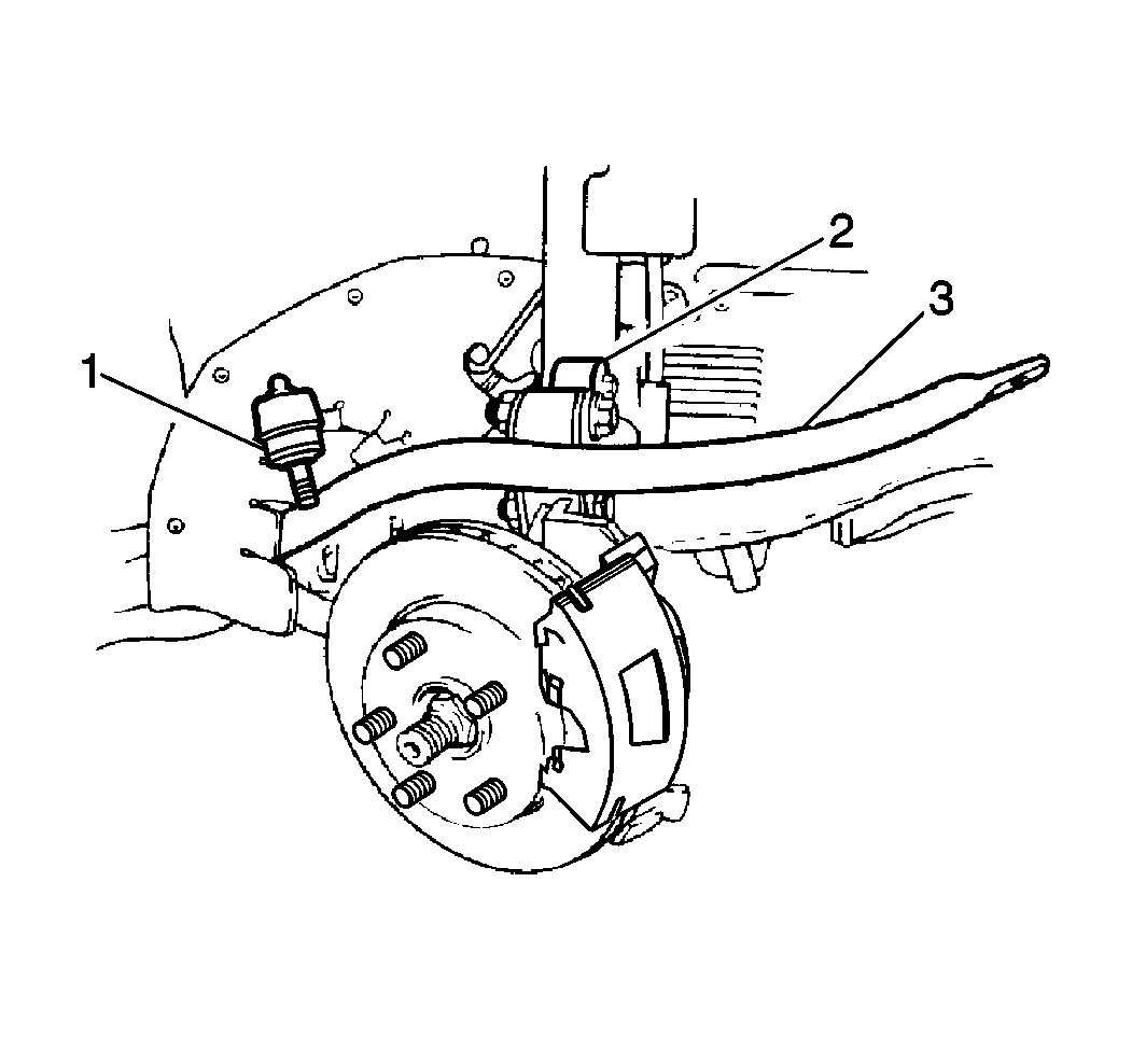
- Remove the left outer tie rod retaining nut.
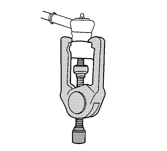
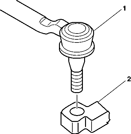
- Use the J 24319-B in order to remove the left tie rod end (1) from the steering knuckle (2).
- Remove the exhaust manifold pipe. Refer to Exhaust Manifold Rear Pipe Replacement .
- Turn the left strut completely to the left. Guide the stabilizer shaft out the left side of the vehicle between the body and the strut.
- Remove the stabilizer shaft (3) from the vehicle.
Installation Procedure
- Install the stabilizer shaft (3) to the vehicle.
- Install the exhaust manifold pipe. Refer to Exhaust Manifold Rear Pipe Replacement .
- Loosely install the following components:
- Install the stabilizer shaft links. Refer to Stabilizer Shaft Link Replacement .
- Install the left tie rod end (1) to the steering knuckle.
- Tighten the following components.
- Install the front tires and wheels. Refer to Tire and Wheel Removal and Installation .
- Lower the vehicle.
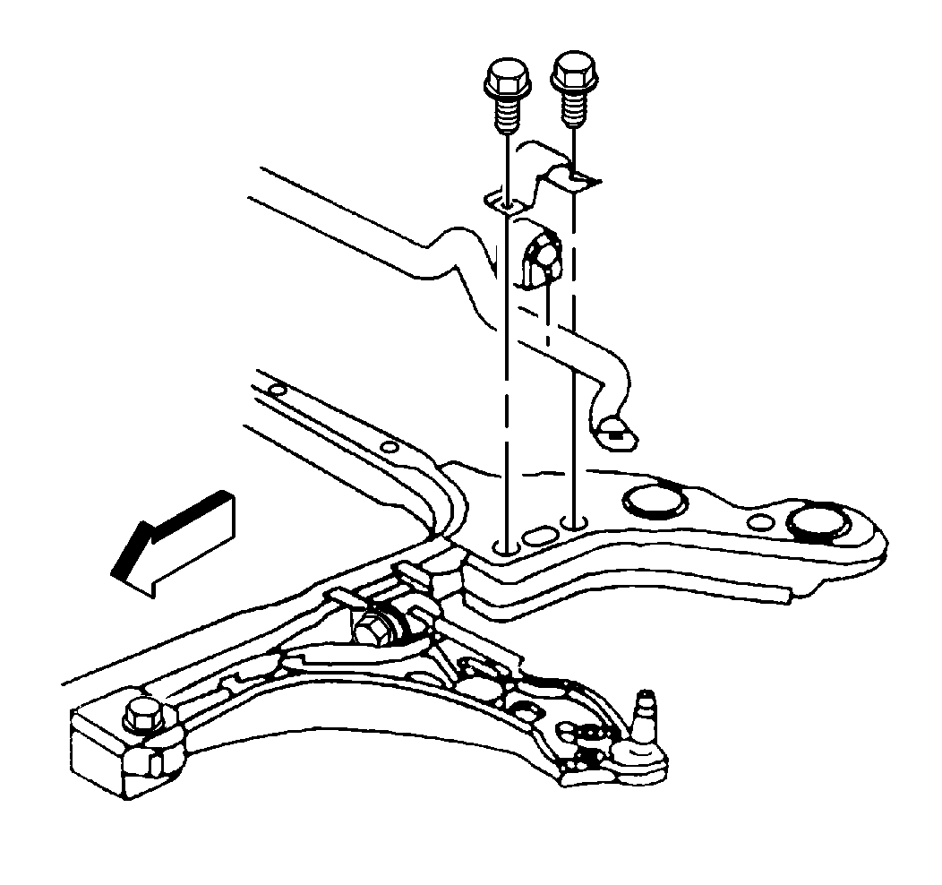
| 3.1. | The left and right stabilizer shaft insulators |
| 3.2. | The stabilizer shaft insulator brackets |
| 3.3. | The stabilizer shaft bracket bolts |
Notice: Use the correct fastener in the correct location. Replacement fasteners must be the correct part number for that application. Fasteners requiring replacement or fasteners requiring the use of thread locking compound or sealant are identified in the service procedure. Do not use paints, lubricants, or corrosion inhibitors on fasteners or fastener joint surfaces unless specified. These coatings affect fastener torque and joint clamping force and may damage the fastener. Use the correct tightening sequence and specifications when installing fasteners in order to avoid damage to parts and systems.
Tighten
| • | Tighten the stabilizer shaft insulator bracket bolts to 50 N·m (37 lb ft). |
| • | Tighten the outer tie rod end to steering knuckle retaining nut to 30 N·m (22 lb ft) plus an additional 200 degrees. |
