GM Service Manual Online
For 1990-2009 cars only
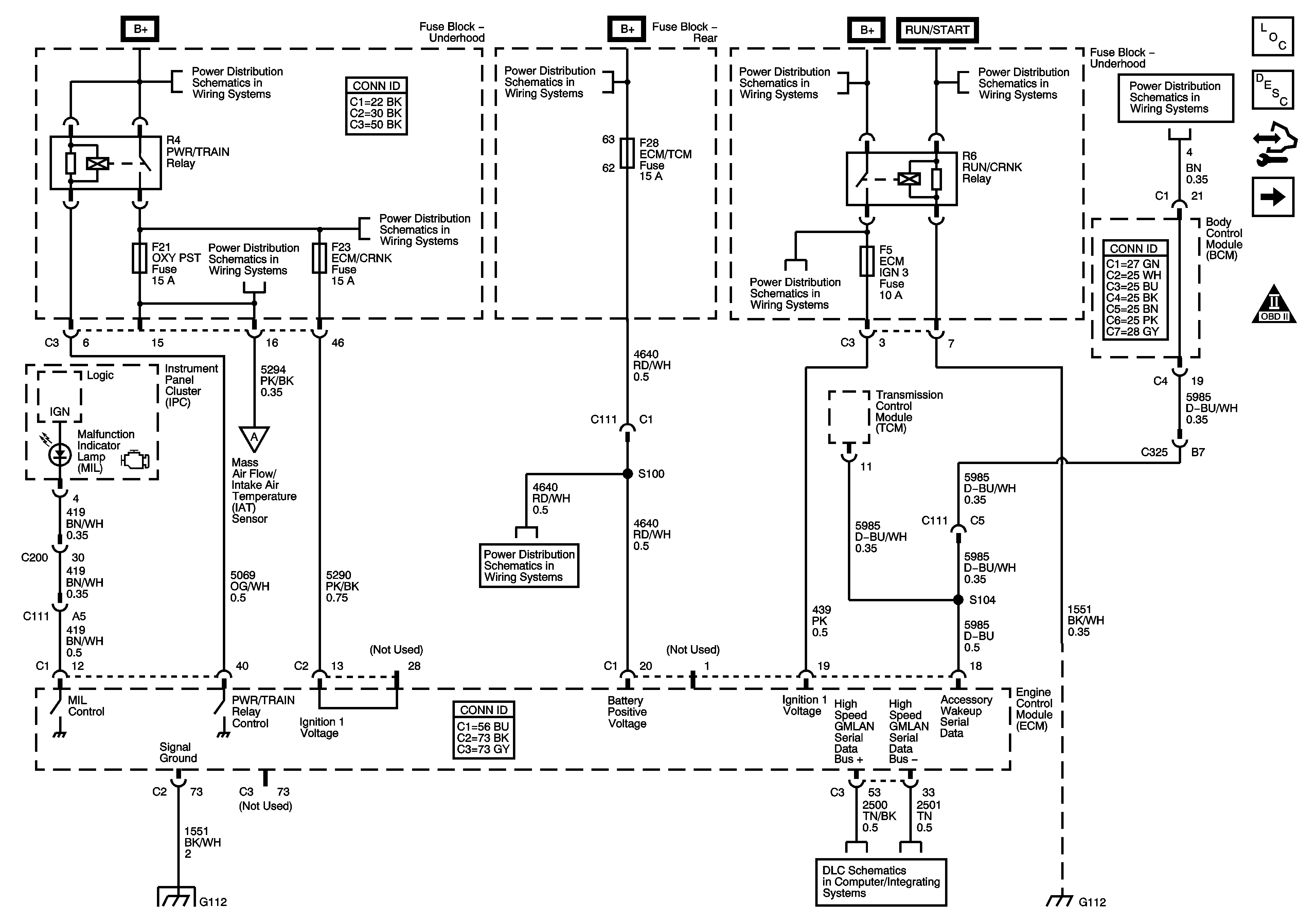
Figure 1:

Power, Ground, MIL and DLC


Object Number: 1680128  Size: FS
Master Electrical Component List
Engine Control Module Description
Control Module References
Engine Data Sensors, 5V Reference Bussing
Engine Controls Schematic Icons
Underhood Fuse Block B+
Rear Fuse Block B+
Underhood Fuse Block B+
RUN/CRANK Relay, TRANS IGN 3, AIRBAG IGN 3, HVAC/IPC, ECM IGN 3 Fuses
IGN SWTCH, STR/WHL/ILLUM Fuses
AIR PUMP, AIR/SOL, A/C, COOL/FAN 2, COOL/FAN, COOL/FAN 1 Relays, INJ/COIL, OXY PST Fuses
Underhood Fuse Block B+
RUN/CRANK Relay, TRANS IGN 3, AIRBAG IGN 3, HVAC/IPC, ECM IGN 3 Fuses
Engine Data Sensors, Pressure, Temp, and MAF/IAT
MSM/RT FRT PWR SEAT, MSM/LT FRT PWR SEAT, MSM Circuit Breakers, ECM/TCM, MSM LOGIC/RF MASSAGE Fuses
G100, G112 (LD8)
High Speed Serial Data
G100, G112 (LD8)
Figure 2:

Engine Data Sensors, 5-Volt Reference Bussing
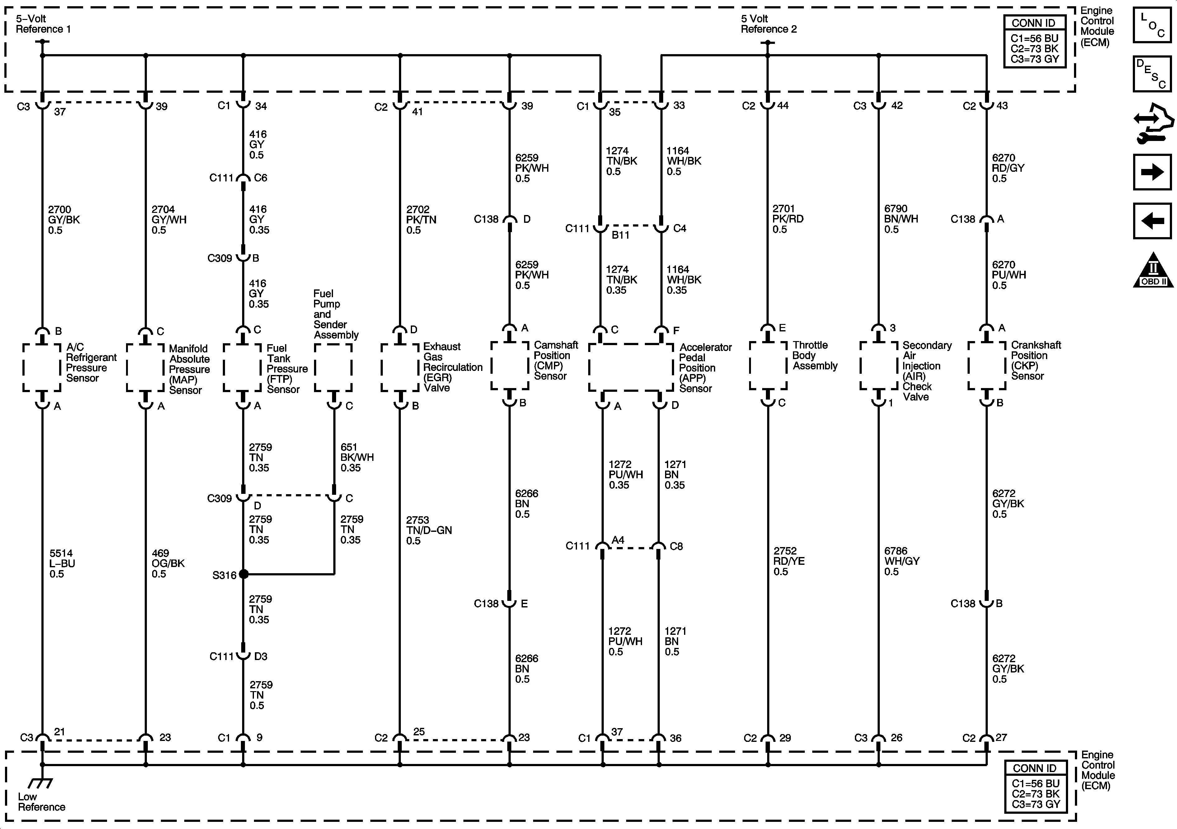

Object Number: 1680130  Size: FS
Master Electrical Component List
Engine Control Module Description
Control Module References
Engine Data Sensors, Pressure, Temp, and MAF/IAT
Power, Ground, MIL, and DLC
Engine Controls Schematic Icons
Figure 3:

Engine Data Sensors - Pressure, Temp and MAF/IAT
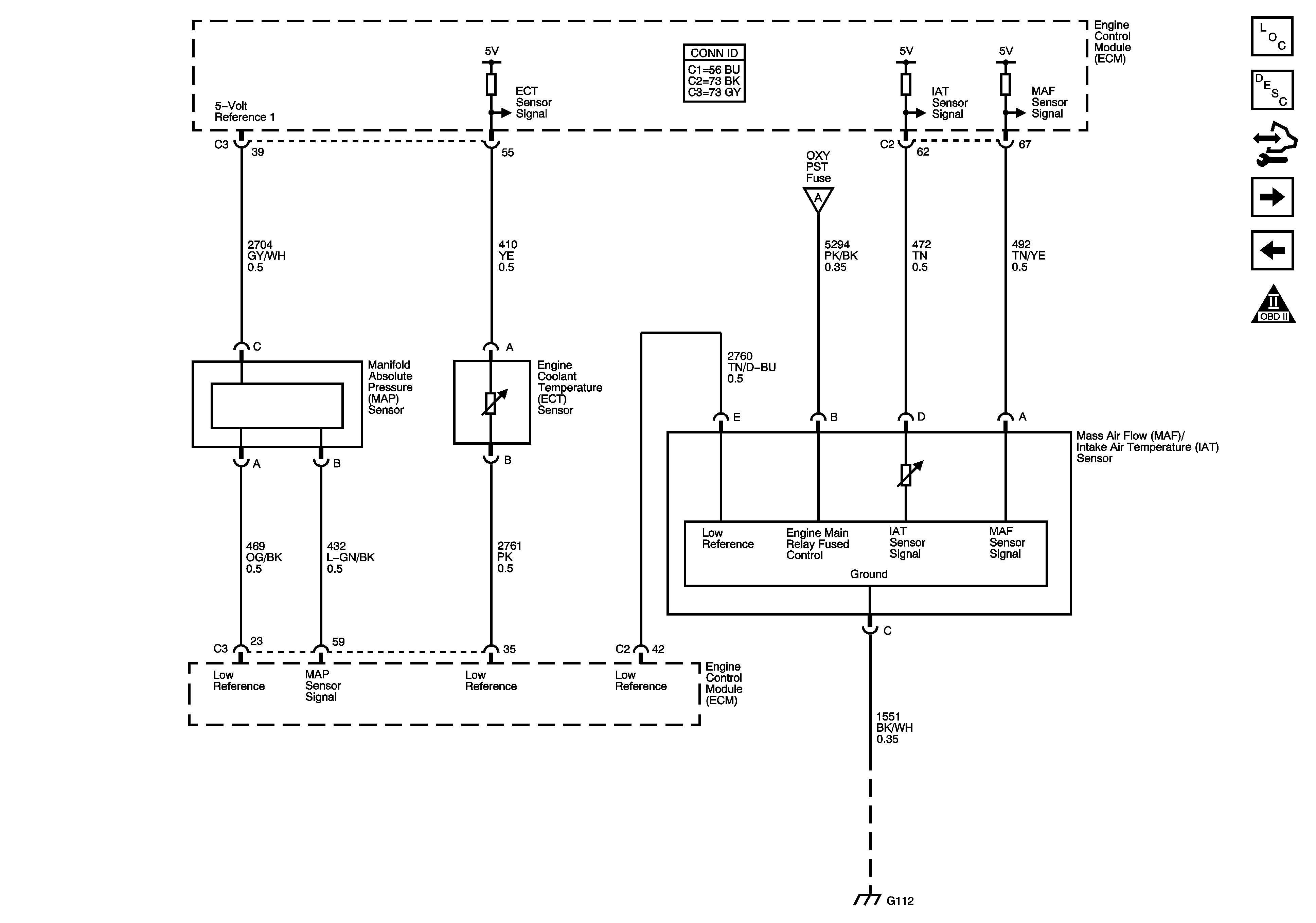

Object Number: 1680132  Size: FS
Master Electrical Component List
Engine Control Module Description
Control Module References
Engine Data Sensors, HO2S
Engine Data Sensors, 5V Reference Bussing
Engine Controls Schematic Icons
Power, Ground, MIL, and DLC
G100, G112 (LD8)
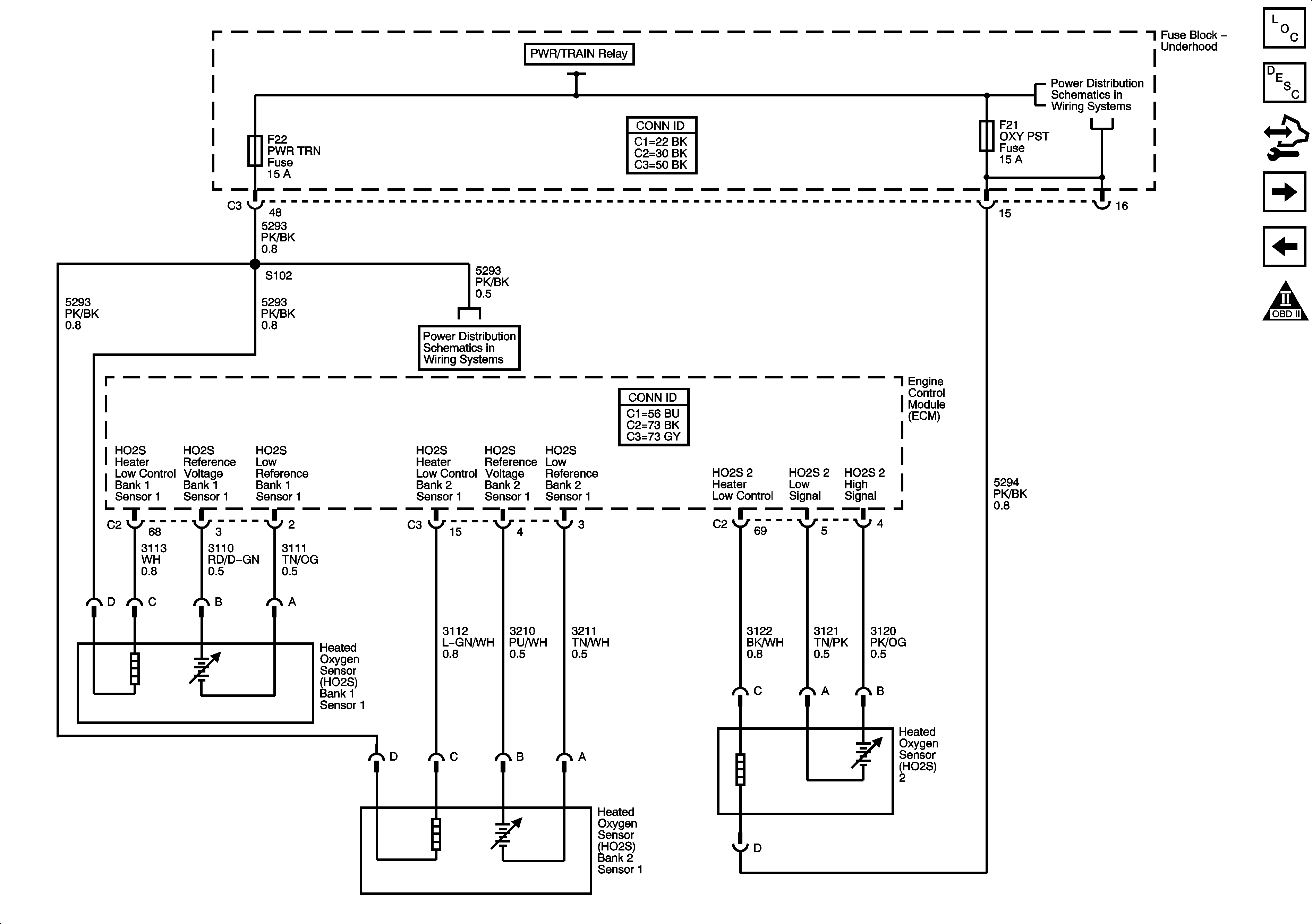
Figure 4:

Engine Data Sensors, HO2S


Object Number: 1680135  Size: FS
Master Electrical Component List
Engine Control Module Description
Control Module References
Engine Data Sensors, APP and Throttle Body Assembly
Engine Data Sensors, Pressure, Temp, and MAF/IAT
Engine Controls Schematic Icons
Underhood Fuse Block B+
AIR PUMP, AIR/SOL, A/C, COOL/FAN 2, COOL/FAN, COOL/FAN 1 Relays, INJ/COIL, OXY PST Fuses
PWR/TRAIN, AIR PUMP, AIR/SOL Relays, ECM/CRNK, INJ/COIL, PWR TRN, AIR PUMP, AIR/SOL Fuses
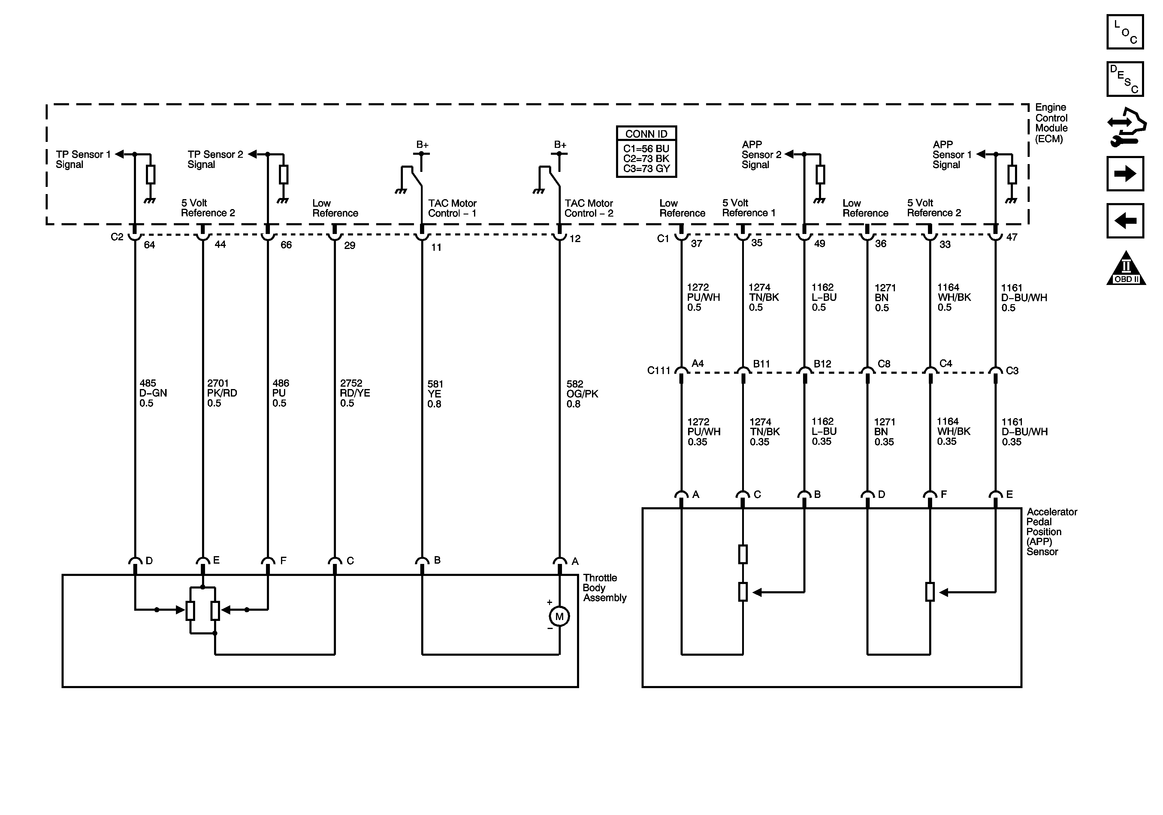
Figure 5:

Engine Data Sensors, APP and Throttle Body Assembly


Object Number: 1680137  Size: FS
Master Electrical Component List
Throttle Actuator Control (TAC) System Description
Control Module References
Ignition Controls, 1 of 2
Engine Data Sensors, HO2S
Engine Controls Schematic Icons
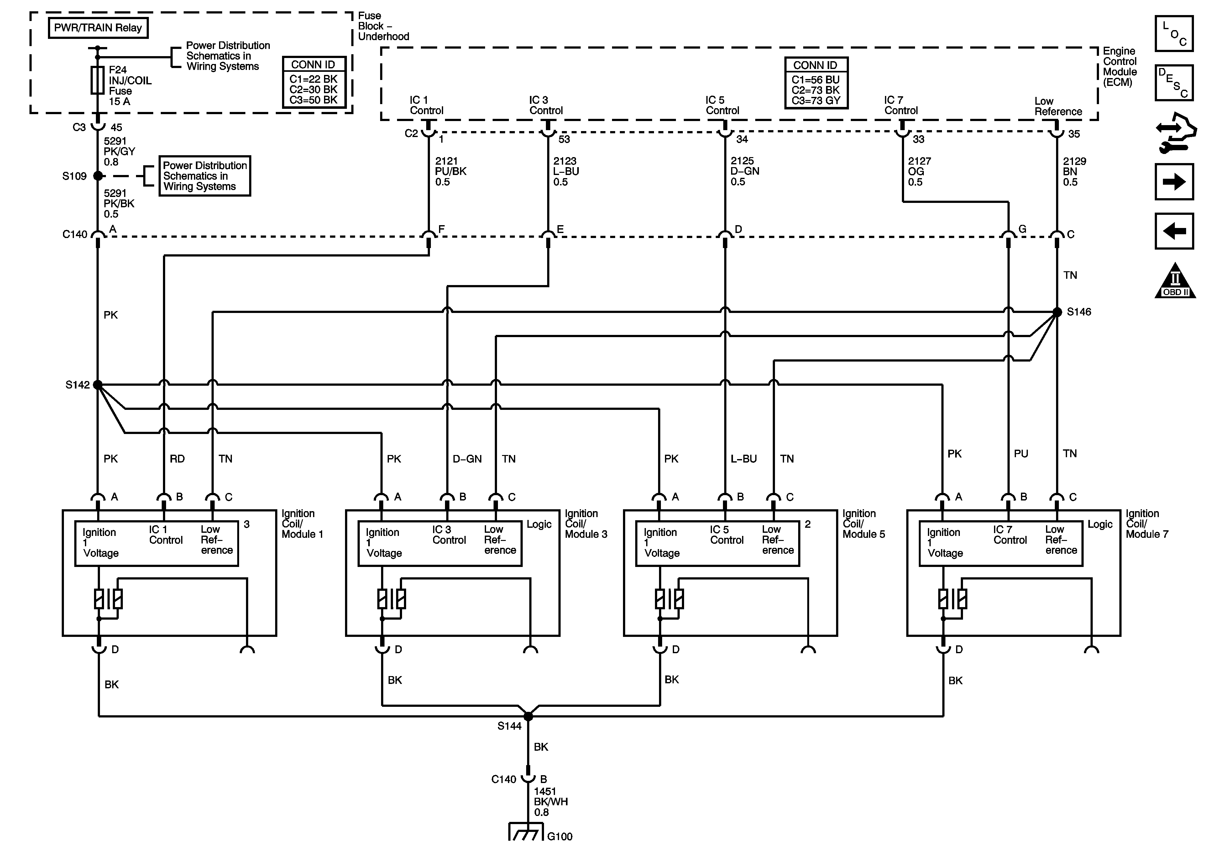
Figure 6:

Ignition Controls - 1 of 2


Object Number: 1680139  Size: FS
Master Electrical Component List
Electronic Ignition (EI) System Description
Control Module References
Ignition Controls, 2 of 2
Engine Data Sensors, APP and Throttle Body Assembly
Engine Controls Schematic Icons
Underhood Fuse Block B+
PWR/TRAIN, AIR PUMP, AIR/SOL Relays, ECM/CRNK, INJ/COIL, PWR TRN, AIR PUMP, AIR/SOL Fuses
G100, G112 (LD8)
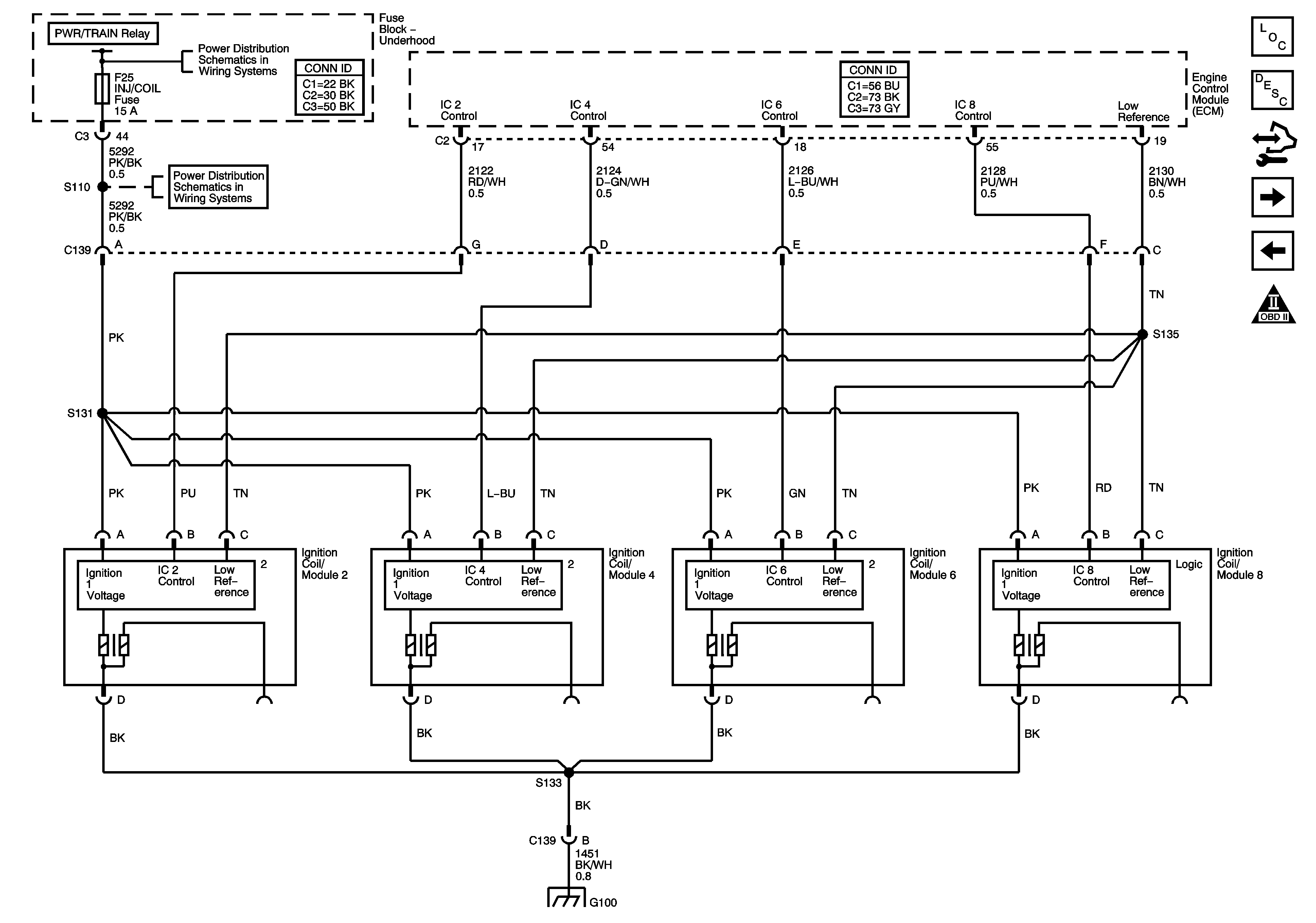
Figure 7:

Ignition Controls - 2 of 2


Object Number: 1704060  Size: FS
Master Electrical Component List
Electronic Ignition (EI) System Description
Control Module References
Fuel Controls
Ignition Controls, 1 of 2
Engine Controls Schematic Icons
Underhood Fuse Block B+
AIR PUMP, AIR/SOL, A/C, COOL/FAN 2, COOL/FAN, COOL/FAN 1 Relays, INJ/COIL, OXY PST Fuses
G100, G112 (LD8)
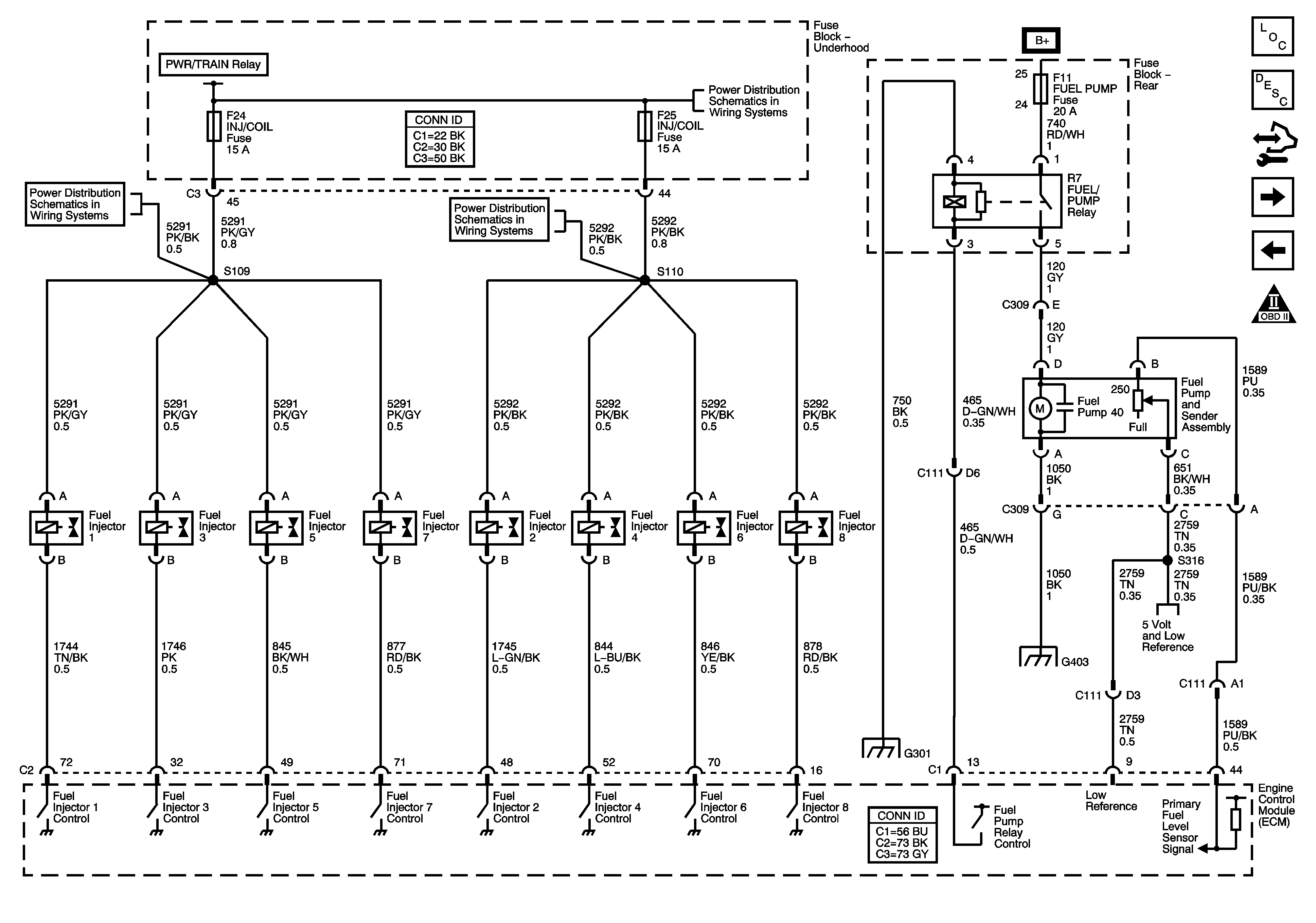
Figure 8:

Fuel Controls


Object Number: 1680142  Size: FS
Master Electrical Component List
Fuel System Description
Control Module References
CKP, CMP, Knock Sensors
Ignition Controls, 2 of 2
Engine Controls Schematic Icons
Underhood Fuse Block B+
PWR/TRAIN, AIR PUMP, AIR/SOL Relays, ECM/CRNK, INJ/COIL, PWR TRN, AIR PUMP, AIR/SOL Fuses
AIR PUMP, AIR/SOL, A/C, COOL/FAN 2, COOL/FAN, COOL/FAN 1 Relays, INJ/COIL, OXY PST Fuses
G301
G403
Engine Data Sensors, 5V Reference Bussing
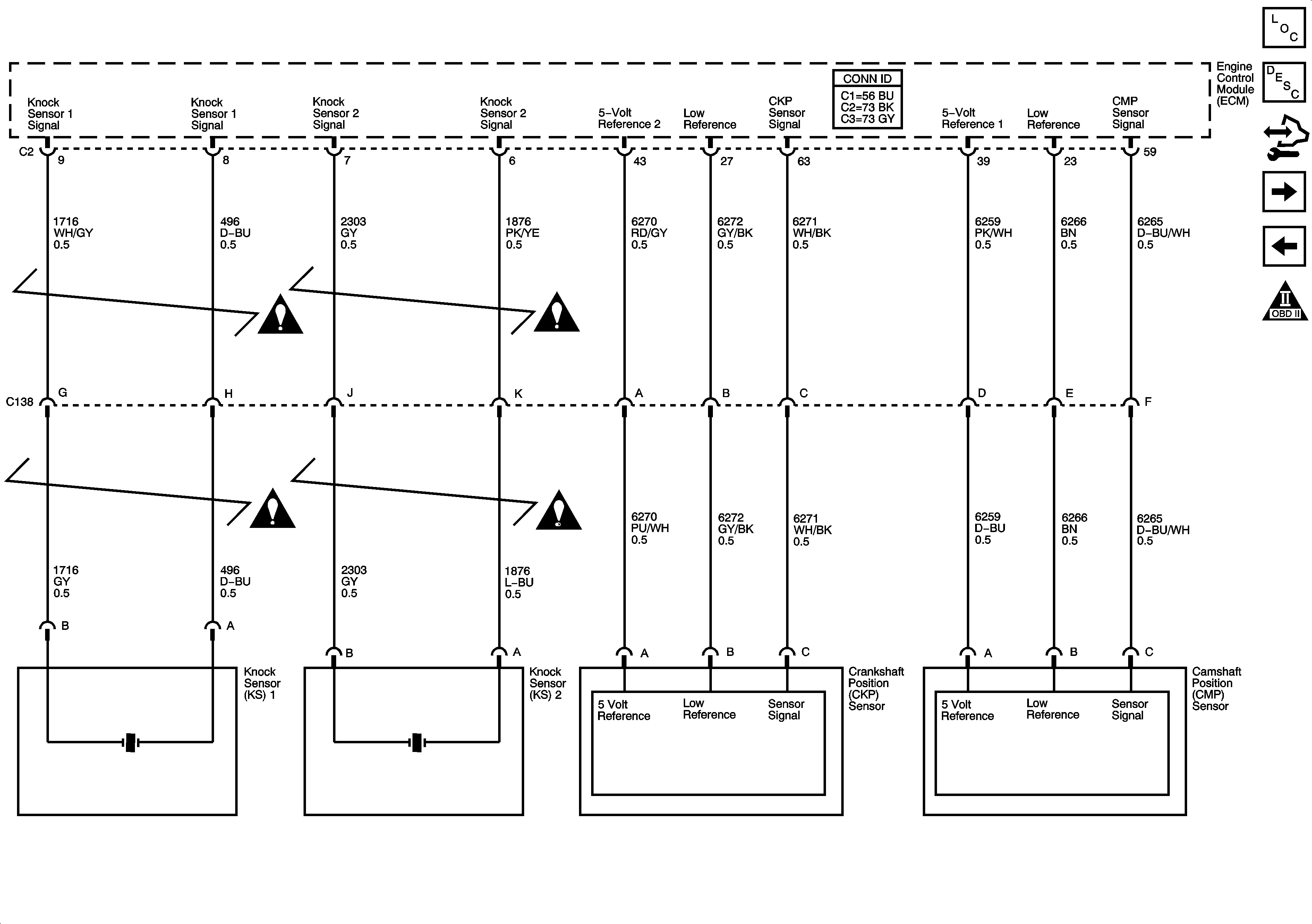
Figure 9:

CKP, CMP, Knock Sensors


Object Number: 1680144  Size: FS
Master Electrical Component List
Engine Control Module Description
Control Module References
EVAP Controls
Fuel Controls
Engine Controls Schematic Icons
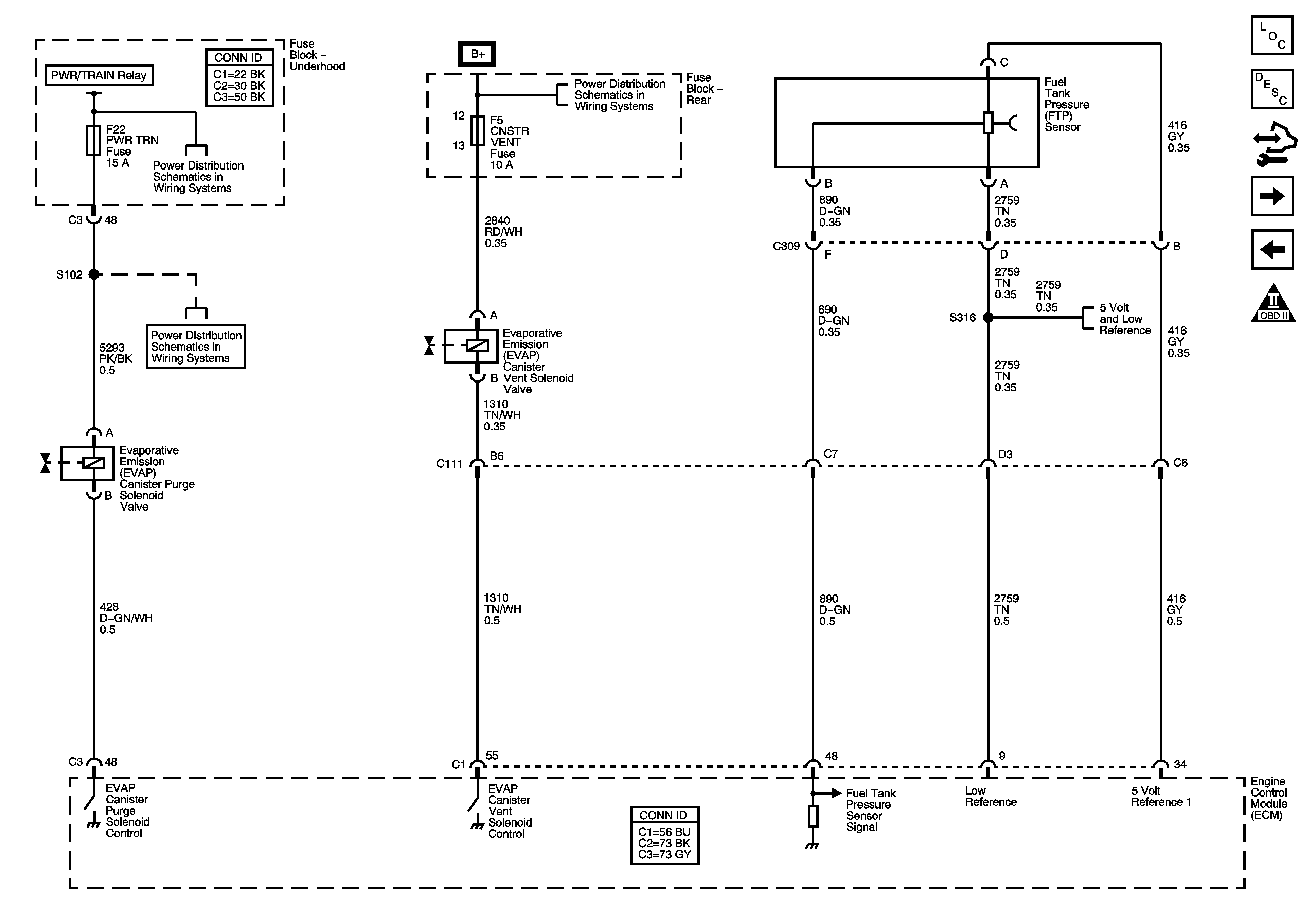
Figure 10:

EVAP Controls


Object Number: 1680147  Size: FS
Master Electrical Component List
Evaporative Emission Control System Description
Control Module References
EGR, Secondary Air Injection (AIR)
CKP, CMP, Knock Sensors
Engine Controls Schematic Icons
Underhood Fuse Block B+
Rear Fuse Block B+
PWR/TRAIN, AIR PUMP, AIR/SOL Relays, ECM/CRNK, INJ/COIL, PWR TRN, AIR PUMP, AIR/SOL Fuses
Engine Data Sensors, 5V Reference Bussing
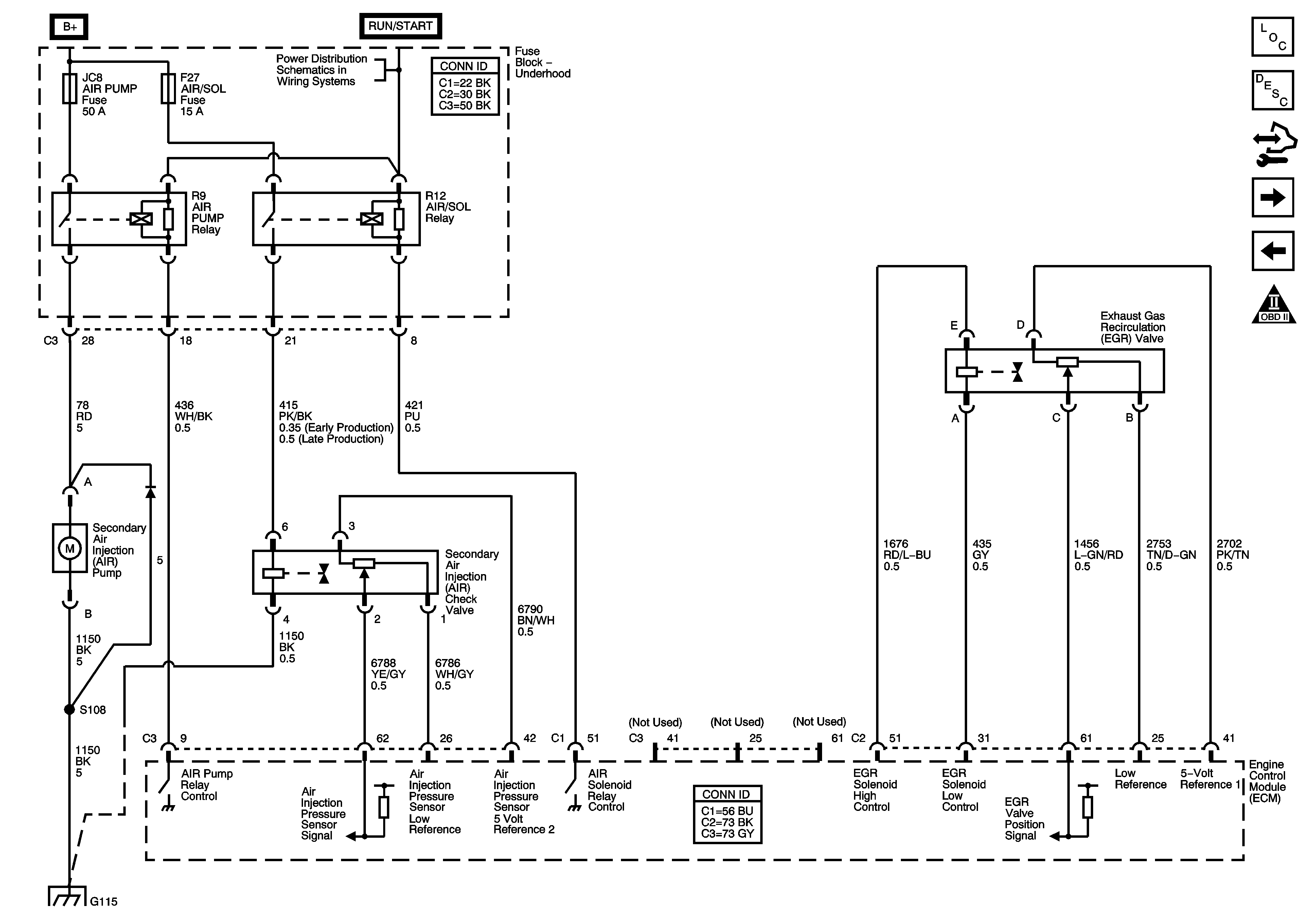
Figure 11:

EGR, Secondary Air Injection (AIR)


Object Number: 1680150  Size: FS
Master Electrical Component List
Secondary Air Injection System Description
Control Module References
Controlled and Monitored Subsystem References
EVAP Controls
Engine Controls Schematic Icons
Underhood Fuse Block B+
G101, G110, G111, G114, G115, G302, G303, G306, G307
Figure 12:

Controlled/Monitored Subsystem References
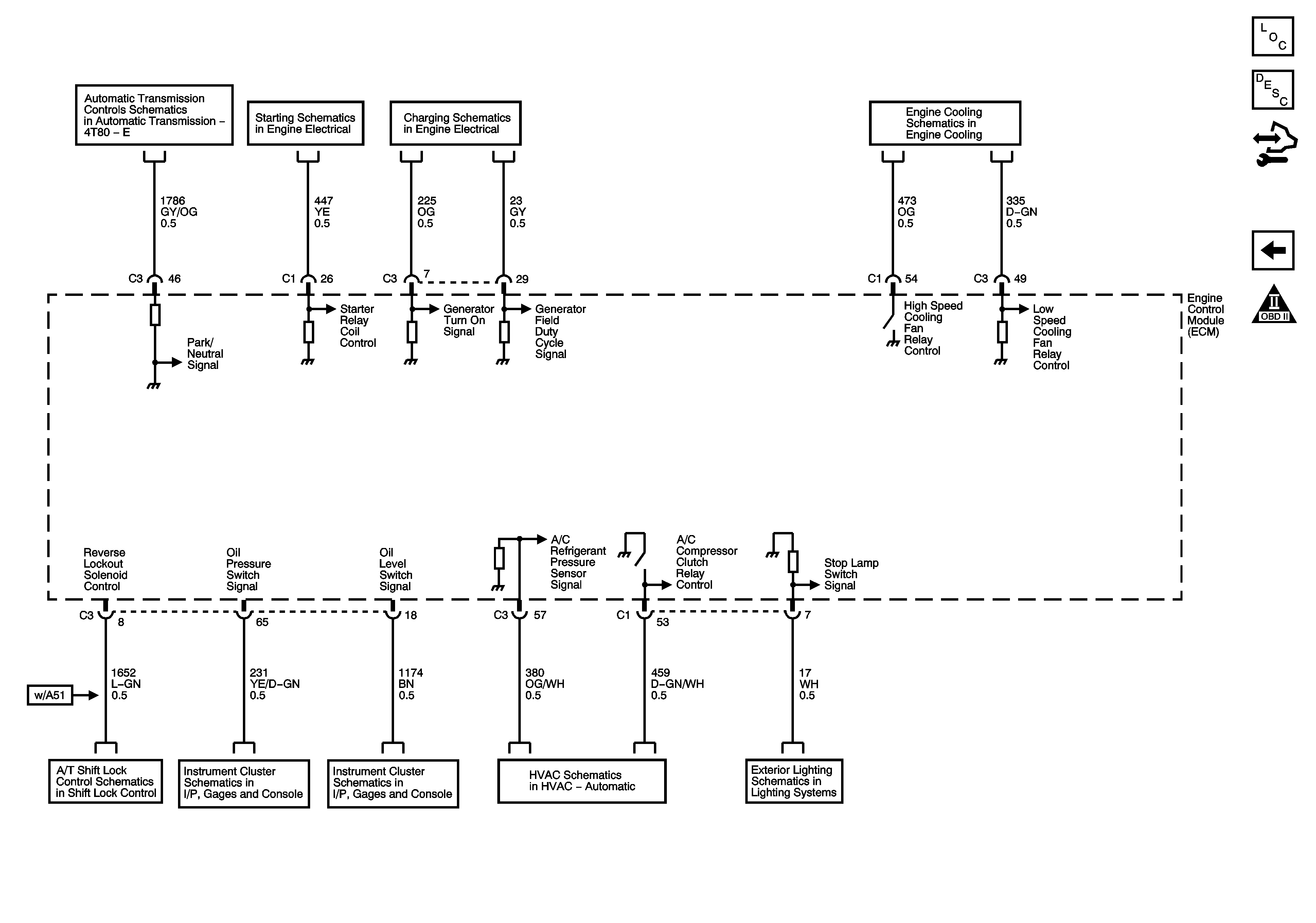

Object Number: 1680153  Size: FS
Master Electrical Component List
Engine Control Module Description
Control Module References
EGR, Secondary Air Injection (AIR)
Engine Controls Schematic Icons
TCM Power and Ground
Starting 1 of 2
Charging
Engine Cooling Schematics
Shift Lock Control Schematics
Oil Level, EOP, Fuel Level Sensor
Compressor Controls
Rear Stop/Turn Signal Lamps